Lock cylinder and unlocking key
A technology for unlocking keys and lock cylinders, which is applied in the field of locks, can solve the problems of low anti-theft performance of mechanical lock cylinders, achieve the effects of increasing complexity and cracking difficulty, increasing technical unlocking difficulty, and increasing complexity
- Summary
- Abstract
- Description
- Claims
- Application Information
AI Technical Summary
Problems solved by technology
Method used
Image
Examples
Embodiment 1
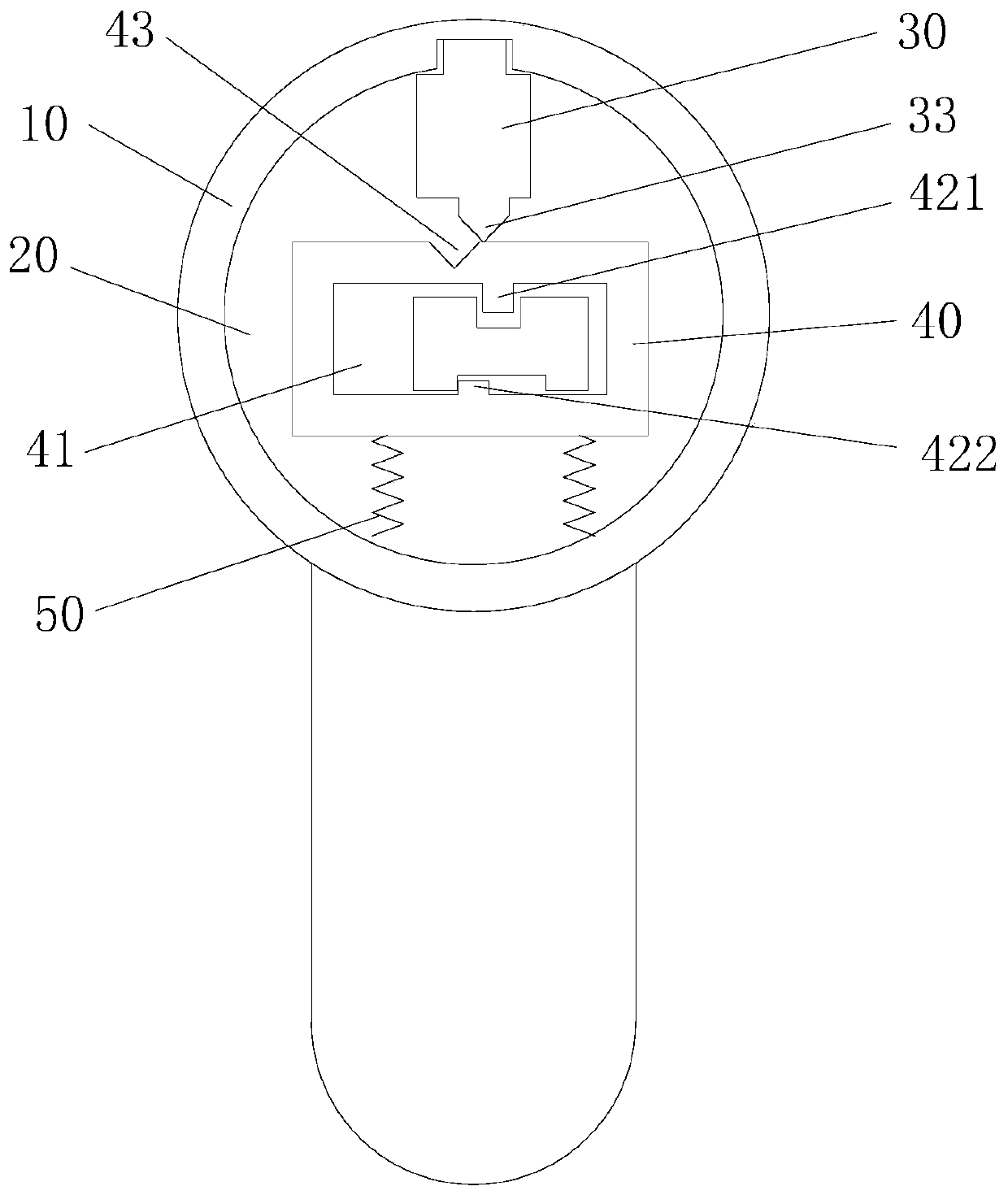
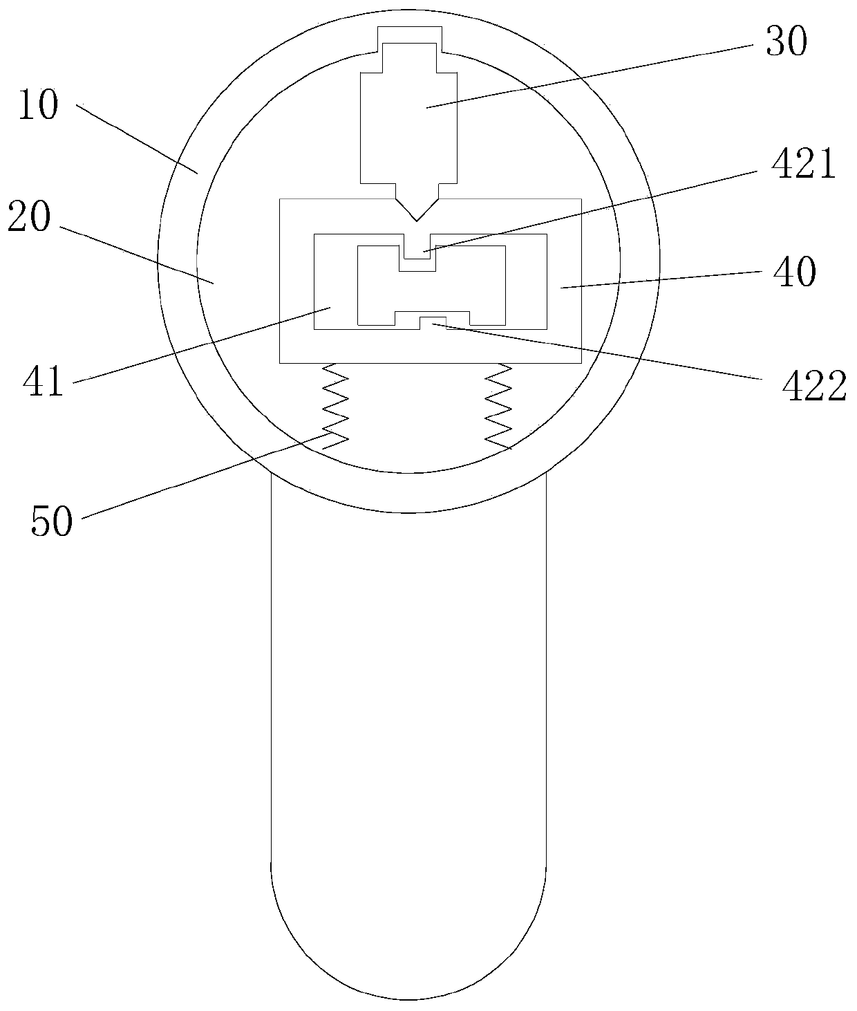
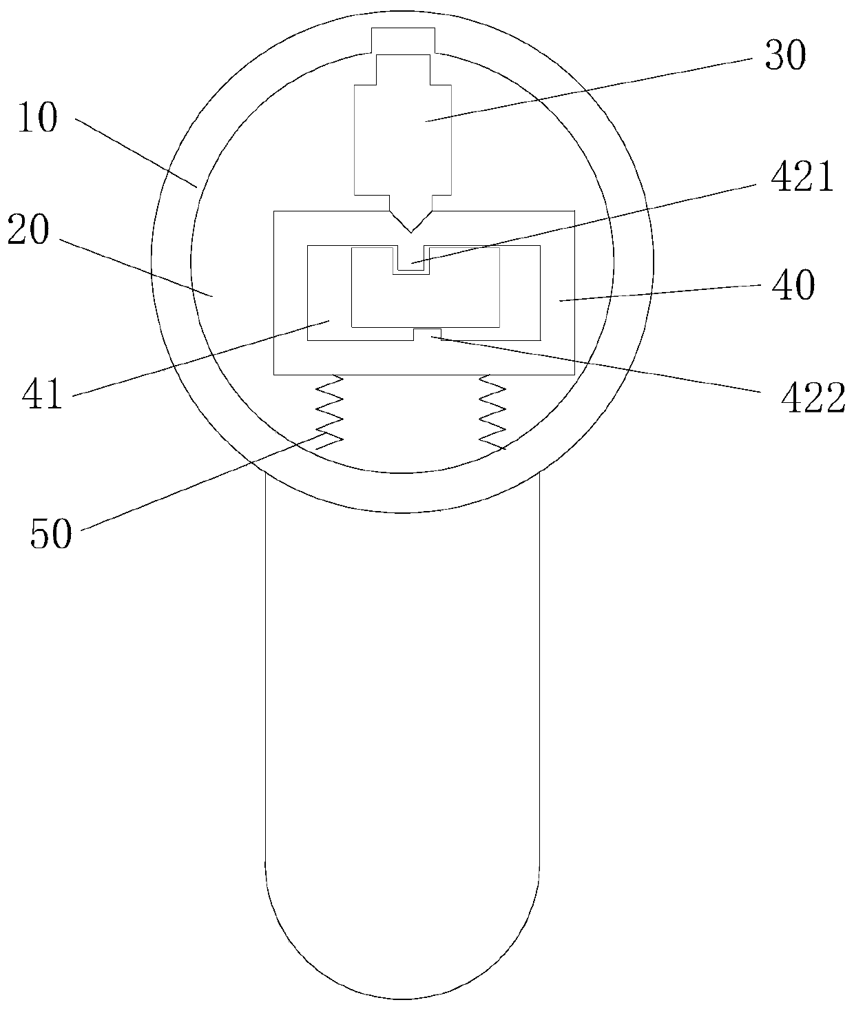
[0042] Such as Figure 1 to Figure 4 A lock cylinder shown includes a lock casing 10, a lock cylinder 20, a lock bolt 30 and a locking blade 40, the lock cylinder 20 is movably arranged in the lock casing 10; the lock bolt 30 is movably arranged between the lock cylinder 20 and the lock casing 10 between, and can be switched between the locked position extending into the lock case 10 and the unlocked position withdrawn from the lock case 10; the locking blade 40 is movably arranged in the lock cylinder 20, and can be between the position of the stopper or the position of avoiding the lock bolt 30 Movement, the locking blade 40 has a movement along the first direction and a movement along the second direction; when the lock cylinder is locked, one end of the lock bolt 30 extends from the lock cylinder 20 into the lock housing 10 to hinder the rotation of the lock cylinder 20 , the locking blade 40 is located at the position of the stopper lock bolt 30, and the other end of the ...
Embodiment 2
[0059] The difference from the first embodiment is that the first driving part 421 and the second driving part 422 are arranged in different positions.
[0060] In this embodiment, the first driving part 421 and the second driving part 422 are arranged on the inner wall of the same side of the unlocking hole 41. It should be noted that the second driving part 422 The position of , needs to remain unchanged, that is, the second driving part 422 should be disposed on the inner wall of the unlocking hole 41 away from the lock bolt 30 . In this case, the first driving part 421 can be arranged on the inner wall of the unlocking hole 41 away from the lock bolt 30, so that the first driving part 421 and the second driving part 422 are arranged on the same side, or even combined into one arrangement. ,Such as Figure 7 to Figure 10 shown. Correspondingly, the two unlocking grooves on the unlocking key are also arranged on the same surface, and even the two unlocking grooves can be c...
Embodiment 3
[0062] The difference from the first embodiment is that this embodiment is additionally equipped with a cylinder lock 60 .
[0063] Such as Figure 11 to Figure 16 As shown, the cylinder sleeve 60 is sleeved on the outside of the cylinder 20, and is located between the cylinder 20 and the lock housing 10, and the cylinder housing 10, the cylinder sleeve 60 and the cylinder 20 can rotate relative to each other, and the lock bolt 30 includes a first section 31 and a second section 32 that abut in sequence, the first section 31 is farther away from the locking blade 40 than the second section 32, a part of the first section 31 can extend into the lock housing 10, and the second section 31 The length of one section 31 is slightly greater than the thickness of the cylinder sleeve 60 .
[0064] When the lock cylinder is not unlocked, the first segment 31 extends into the lock housing 10, and the interface between the first segment 31 and the second segment 32 coincides with the int...
PUM
 Abstract
Description
Claims
Application Information
 - R&D Engineer
- R&D Manager
- IP Professional
- Industry Leading Data Capabilities
- Powerful AI technology
- Patent DNA Extraction
Browse by: Latest US Patents, China's latest patents, Technical Efficacy Thesaurus, Application Domain, Technology Topic, Popular Technical Reports.
© 2024 PatSnap. All rights reserved.Legal|Privacy policy|Modern Slavery Act Transparency Statement|Sitemap|About US| Contact US: help@patsnap.com


