
Non-pumping-stopping automatic collide pump mechanism for pumping unit

A kind of pumping unit, automatic technology, applied in the direction of production fluid, wellbore/well parts, earthwork drilling and production, etc., can solve the problems of production fluctuation, easy to cause dangerous accidents, affect the normal production of oil wells, etc.

Pending Publication Date: 2019-11-15
陈志国 +1
View PDF0 Cites 0 Cited by
  • Summary
  • Abstract
  • Description
  • Claims
  • Application Information

AI Technical Summary

Problems solved by technology

[0003] The technical problem to be solved by the present invention is to provide a non-stop pumping automatic pumping mechanism, which solves the problem that the current beam pumping unit needs to be stopped for manual operation to touch the pump, which is easy to cause dangerous accidents and well jamming, thus Cause damage or even burn out circuit equipment, affect the normal production of oil wells, and cause production fluctuations

Method used

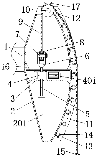
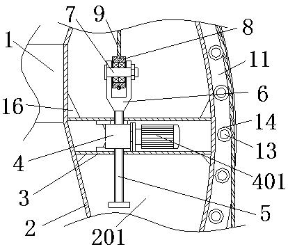
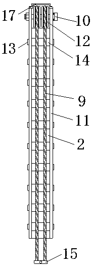

Image

  • Non-pumping-stopping automatic collide pump mechanism for pumping unit
  • Non-pumping-stopping automatic collide pump mechanism for pumping unit
  • Non-pumping-stopping automatic collide pump mechanism for pumping unit

Examples


Embodiment Construction

[0018] In order to make the objectives, technical solutions and advantages of the present invention clearer, the following further describes the present invention in detail with reference to the accompanying drawings and embodiments. It should be understood that the specific embodiments described herein are only used to explain the present invention, but not to limit the present invention.

[0019] In the description of the present invention, it should be understood that the terms "longitudinal", "lateral", "upper", "lower", "front", "rear", "left", "right", "vertical", The orientation or positional relationship indicated by "horizontal", "top", "bottom", "inner", "outer", etc. are based on the orientation or positional relationship shown in the drawings, and are only for the convenience of describing the present invention, rather than indicating or It is implied that the device or element referred to must have a specific orientation, be configured and operated in a specific orie...


PUM


Abstract

The invention discloses a non-pumping-stopping automatic collide pump mechanism for a pumping unit. The non-pumping-stopping automatic collide pump mechanism for the pumping unit comprises a pumping beam, a horse head, a mounting shell, a screw lift and a screw rod. The horse head is fixedly connected to the right end of the pumping beam, a cavity is formed in the horse head, a through hole is formed in the top end of the cavity, the right side of the horse head is a circular arc surface, the top end of the horse head and the front side and the back side of the right side of the horse head aresymmetrically fixedly connected with baffles separately, a connecting shaft II is fixedly connected between the top ends of the baffles, two pulleys are rotatably connected to the connecting shaft IIthrough bearings in a front-and-rear symmetrical mode, and a connecting shaft III is fixedly connected between the two baffles on the right side of the horse head. A small roller is rotatably connected to the connecting shaft III through the bearings, and the mounting shell is fixedly connected to the middle of the cavity. The screw lift is fixedly connected into the mounting shell, and a liftingmotor is fixedly connected with a power input port on the right side of the screw lift. The non-pumping-stopping automatic collide pump mechanism for the pumping unit is scientific and reasonable instructure, convenient to operate, low in production cost, and is suitable for popularization.

Description

Technical field [0001] The invention relates to the field of oil extraction machinery, in particular to an automatic bumping mechanism for an oil pumping unit without stopping. Background technique [0002] The beam pumping unit is currently the main machinery for oil production in oil production. The main operating mode of the beam pumping unit is to swing the beam up and down to drive the donkey head at the end of the beam to swing up and down. The end will be fixedly connected to the sucker rod by a hair braid, and the hair braid and the sucker rod are fixedly connected by a polished rod clip. When the donkey head swings up and down, the hair braid will also drive the sucker rod to twitch up and down in the vertical direction. , When the sucker rod is pumped up and down, the pumping equipment below is driven to extract oil. The pumping unit bumps the pump is an operation that needs to be carried out frequently during the production and operation of the beam pumping unit. Norma...

Claims


Application Information

Patent Timeline
Patent Type & Authority Applications(China)
IPC IPC(8): E21B43/00
CPCE21B43/127
Inventor 王艳陈研迪王跃歧
Owner 陈志国
Learn More