Large-size imbricate cell structure

A large-scale, battery technology, applied in circuits, electrical components, photovoltaic power generation, etc., can solve the problems of bumps and fragments, battery bending, etc., to reduce the amount of bumps or fragments, improve the yield, and reduce the risk of component rework. Effect

Pending Publication Date: 2019-11-15
DONGFANG HUANSHENG PHOTOVOLTAIC (JIANGSU) CO LTD
View PDF0 Cites 0 Cited by
  • Summary
  • Abstract
  • Description
  • Claims
  • Application Information

AI Technical Summary

Problems solved by technology

[0003] The problem to be solved by the present invention is to provide a large-size shingled battery structure, especially suitable for shingled batteries with a silicon wafer size greater than 156 mm, which can not only solve the technical problem of battery bending in current silicon wafer printing, but also solve Eliminate the technical problems of bumps and debris during later assembly, ensure product quality, improve the yield of shingled batteries, and reduce production costs

Method used


Image

  • Large-size imbricate cell structure
  • Large-size imbricate cell structure
  • Large-size imbricate cell structure

Examples


Embodiment Construction

[0026] The present invention will be described in detail below in conjunction with the accompanying drawings and specific embodiments.

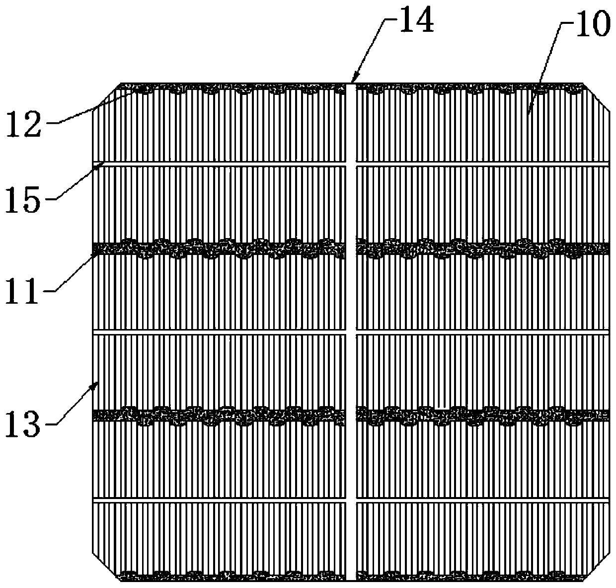
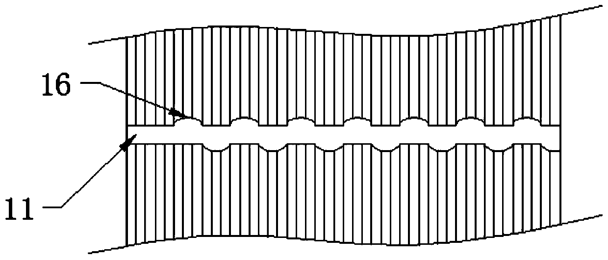
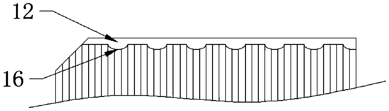
[0027] The present invention proposes a large-scale shingled battery structure, such as Figure 1-5 As shown, it includes a front side 10 and a back field 20. The front side 10 includes several first main grids 11 and second main grids 12 arranged in parallel. The first main grid 11 is located inside the front side 10, and the second main grids 12 are respectively located upper and lower edges, specifically as figure 1 shown. The back field 20 includes a plurality of back electrodes 21 arranged in parallel. The back electrodes 21 are arranged in parallel with the first main gate 11 and offset. The structure of the back electrodes 21 is the same as that of the first main gate 11 . In this embodiment, there are two first main grids 11 and two second main grids 12, the first main grids 11 are respectively located on the upper half and the lowe...


PUM


Abstract

The invention provides a large-size imbricate cell structure, which includes a front and a back field. The front includes a number of first main grids and second main grids which are arranged in parallel. The first main grids are located on the inner side of the front, and the second main grids are located at the upper and lower edges of the front. The back field includes a number of back electrodes which are arranged in parallel, and the back electrodes and the first main grids are arranged in parallel and staggered. The front is also provided with at least one first channel and second channel. The first channel is perpendicular to the first main grids and runs through the first main grids and the second main grids. The second channels are arranged in parallel with the first main grids and are cross-communicated with the first channel. The back field is also provided with at least one third channel and fourth channel, the third channel is arranged opposite to the first channel, and the fourth channels are arranged opposite to the first main grids. The back electrodes are arranged opposite to the second channels. The problems of cell bending and hidden crack are solved, and the problems of collision and fragmentation in the later assembly are solved. The product quality is guaranteed, the yield of imbricate cells is improved, and the production cost is reduced.

Description

technical field [0001] The invention belongs to the technical field of solar battery shingled components, and in particular relates to a large-size shingled battery structure. Background technique [0002] Existing shingled battery components are all assembled from small-sized silicon wafers, and the side length of the small-sized silicon wafers is 156 mm. However, with the development of the photovoltaic market, the requirements for solar cell components are getting higher and higher, and the shingled cell components tend to have high power and high conversion rate. However, the existing small-sized silicon wafers have small effective areas and low cell conversion rates, which cannot meet the technical requirements for assembly of existing solar cells. The effective area of ​​a single large-sized silicon wafer is larger, which can increase the effective power generation area of ​​the solar cell module, which is the current research and development trend. While the existin...

Claims


Application Information

Patent Timeline
IPC IPC(8): H01L31/0224H01L31/042
CPCH01L31/022425H01L31/042Y02E10/50
Inventor 刘田丰吴俊清刘大伟涂文辉
Owner DONGFANG HUANSHENG PHOTOVOLTAIC (JIANGSU) CO LTD
Why Eureka
Try Eureka