Supercharge Your Innovation With Domain-Expert AI Agents!

a floating connector

A technology of floating connectors and connectors, which is applied in the direction of connection, installation of connection parts, parts of connection devices, etc. It can solve the problems of circular floating connectors, such as shape restrictions, large overall structure, and improper mating, etc., to achieve improved Effects of radial floating reliability, improved floating reliability, and guaranteed effectiveness

Active Publication Date: 2021-01-22
GUIZHOU SPACE APPLIANCE CO LTD
View PDF6 Cites 0 Cited by
  • Summary
  • Abstract
  • Description
  • Claims
  • Application Information

AI Technical Summary

Problems solved by technology

However, in the actual application process, the equipment that fixes the plug and the socket is often displaced due to processing errors or matching errors, which leads to the inability of the connectors to be mated accurately or in place, and eventually leads to damage to the connectors or failure to achieve reliable electrical contact.
[0003] In order to solve the above problems, a large number of floating connectors that can realize floating in X, Y, and Z directions at the same time are widely used at present, while the existing circular floating connectors generally use connectors to be installed into the floating limit inside the floating device, and the overall structure is relatively large , and the floating form is only suitable for circular, square or relatively regular installation spaces. In installation spaces with large differences in length and width or other special-shaped installation spaces, such as "T"-shaped installation spaces, the existing circular floating connectors are limited by their shape , unable to achieve large floating in the X and Y directions, the utilization rate of the structural space is low, and the application is limited

Method used


Image

  • a floating connector
  • a floating connector
  • a floating connector

Examples


Embodiment Construction

[0044] The technical solution of the present invention is further described below, but the scope of protection is not limited to the description.

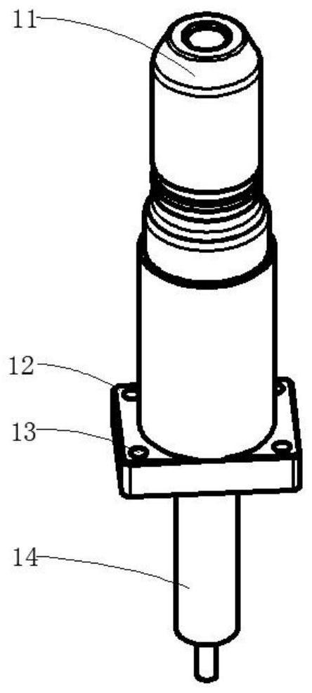
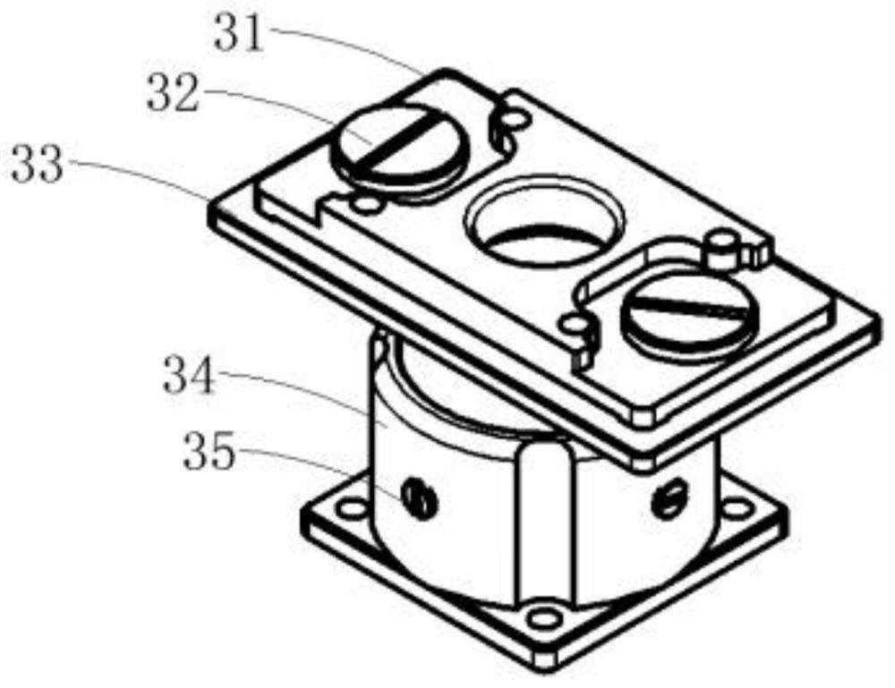
[0045] Such as Figure 1-12 As shown, a floating connector includes a connector 1 and a floating device 3, the connector 1 and the floating device 3 are two bodies, the floating device 3 includes a floating plate 31, a mounting plate 33 and a floating screw 32, the floating The screw 32 is fixed on the mounting plate 33, the floating plate 31 is limited on the mounting plate 33 by the floating screw 32, and the connector 1 is fixed on the floating plate 31 of the floating device 3 through the locking assembly 2;

[0046] The floating device 3 also includes a floating sleeve 34, a top wave spring 36, and a positioning screw 35. The top wave spring 36 is installed in the counterbore 334 of the mounting plate 33, and the cylinder 333 at the lower end of the mounting plate 33 compresses the top wave spring 36. Finally, install the flo...


PUM


Abstract

A floating connector includes a connector and a floating device. The connector is fixed on the upper end face of the floating device by a locking assembly. The floating device includes a floating plate, a mounting plate and floating screws. The floating screw is fixed on the mounting plate, and the floating plate is limited on the mounting plate by the floating screws. The floating device also includes a floating sleeve, an opposite-jacking wave spring and positioning screws. The opposite-jacking wave spring is mounted in a counter bore of the mounting plate. A cylinder 1 at the lower end of the mounting plate compresses the top wave spring and is then installed in the floating sleeve and limited by the positioning screws. The connector can float largely in the X, Y and Z directions in a 'T'-shaped mounting space, and can meet special installation and use requirements.

Description

technical field [0001] The invention belongs to the technical field of connectors, in particular to a floating connector. Background technique [0002] In various electronic systems, electrical connectors are the link to realize the electrical connection between various devices or systems, and are the basic components necessary to form a complete system. However, in the actual application process, the equipment that fixes the plug and the socket is often displaced due to processing errors or matching errors, which leads to the inability of the connectors to be mated accurately or in place, and eventually leads to damage to the connectors or failure to achieve reliable electrical contact. . [0003] In order to solve the above problems, a large number of floating connectors that can realize floating in X, Y, and Z directions at the same time are widely used at present, while the existing circular floating connectors generally use connectors to be installed into the floating ...

Claims


Application Information

Patent Timeline
Patent Type & Authority Patents(China)
IPC IPC(8): H01R13/631H01R13/74
CPCH01R13/631H01R13/6315H01R13/74
Inventor 何国兵黄俊才
Owner GUIZHOU SPACE APPLIANCE CO LTD
Features
  • R&D
  • Intellectual Property
  • Life Sciences
  • Materials
  • Tech Scout
  • Unparalleled Data Quality
  • Higher Quality Content
  • 60% Fewer Hallucinations
Learn More