Supercharge Your Innovation With Domain-Expert AI Agents!

Sliding rail assembly and sliding rail kit thereof

A slide rail assembly and slide rail technology, which is applied to furniture parts, household appliances, drawers, etc., can solve problems such as unsmooth operation

Pending Publication Date: 2019-11-19
KING SLIDE WORKS CO LTD +1
View PDF9 Cites 1 Cited by
  • Summary
  • Abstract
  • Description
  • Claims
  • Application Information

AI Technical Summary

Problems solved by technology

[0004] Although the operation of the locking mechanism 160 of the aforementioned patent does not interfere with the operation of the release mechanism 94, it is necessary to step over the locking mechanism 160 when operating the release mechanism 94, which is obviously not easy to operate.

Method used


Image

  • Sliding rail assembly and sliding rail kit thereof
  • Sliding rail assembly and sliding rail kit thereof
  • Sliding rail assembly and sliding rail kit thereof

Examples


Embodiment Construction

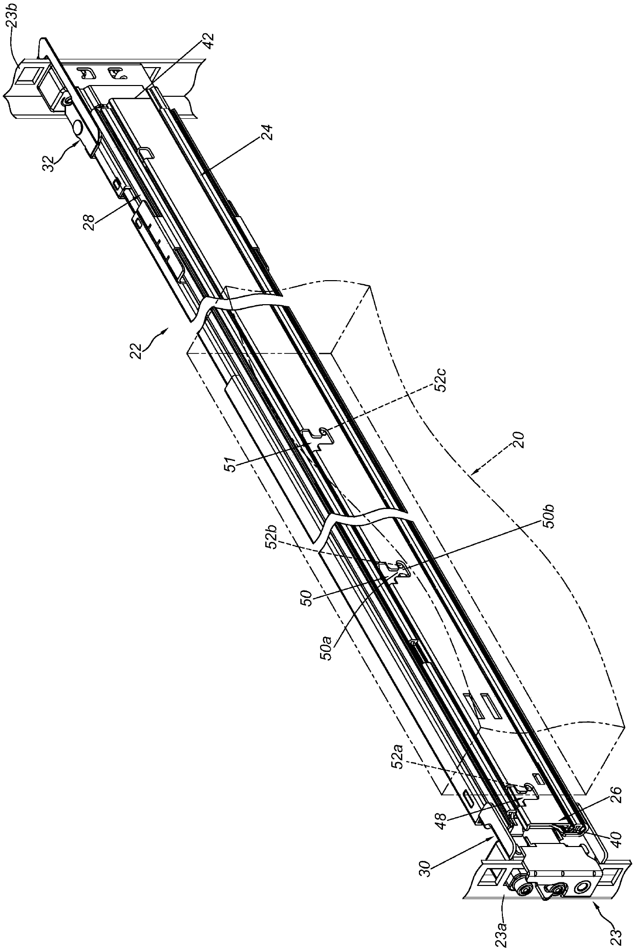
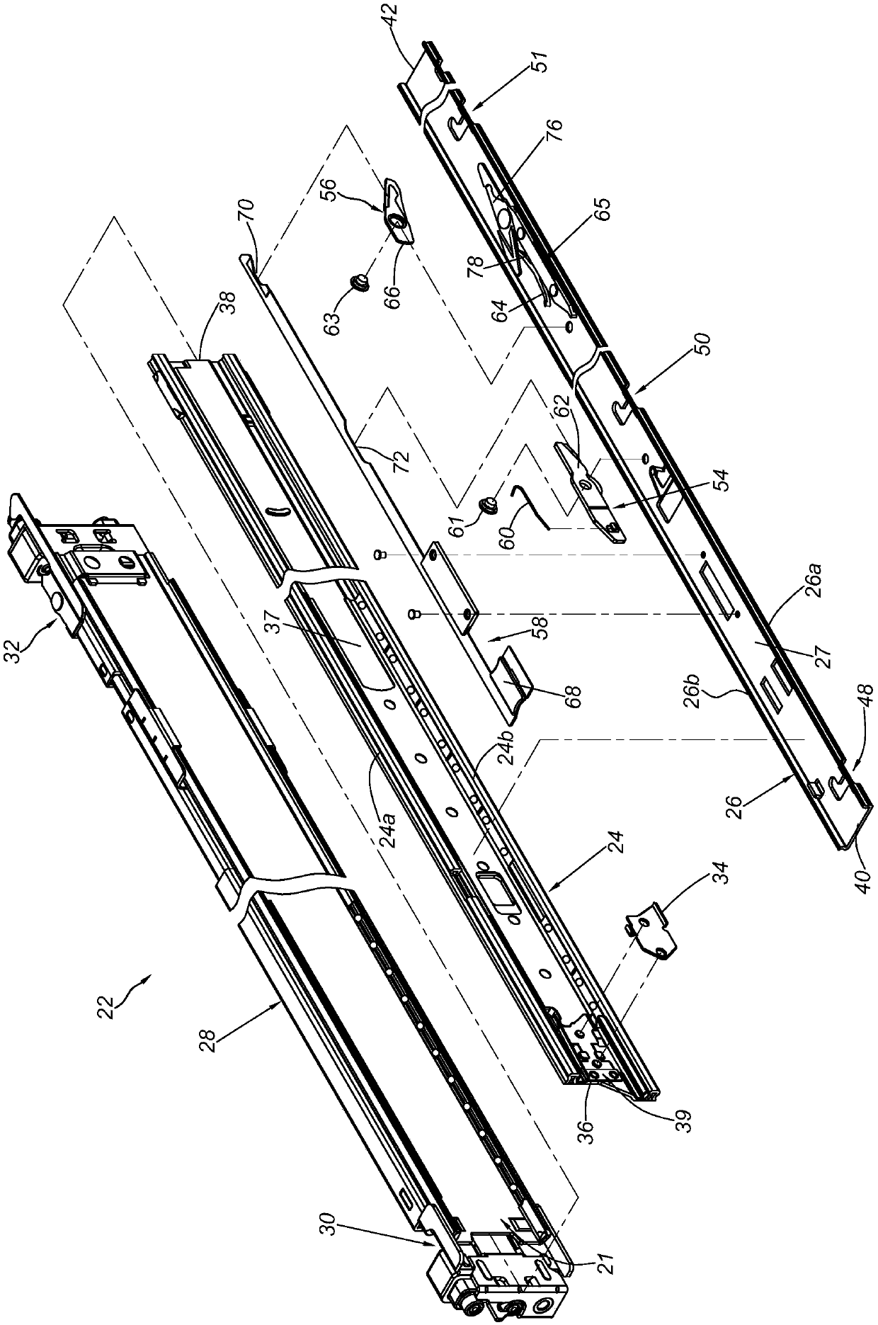
[0031] like figure 1 and figure 2 As shown, in a rack system, a load 20 can be mounted to a rack 23 (rack) through a slide rail assembly 22 . The carrier 20 is, for example, an electronic device, a chassis, or a drawer. The slide rail assembly 22 includes a first rail 24 and a second rail 26 displaceable longitudinally relative to the first rail 24 . Preferably, a third rail 28 is also included. Wherein, the first rail 24 is movably installed between the third rail 28 and the second rail 26 .

[0032] The third rail 28 can be mounted to a first column 23 a and a second column 23 b of the rack 23 through a first bracket 30 and a second bracket 32 ​​. Furthermore, the third rail 28 has a channel 21 .

[0033] The first rail 24 is movably mounted to the channel 21 of the third rail 28 . A stop 34 is arranged on the first rail 24 . The blocking portion 34 is located between a first end 36 (eg front end) and a second end 38 (eg rear end) of the first rail 24 . Preferably,...


PUM


Abstract

The invention relates to a slide rail assembly. The slide rail assembly comprises a first rail, a second rail, a first mechanism, a second mechanism and a release connecting rod. The first rail is provided with a blocking part. The second rail comprises a first end, a second end and a plurality of grooves between the two ends. The first mechanism is arranged on the second rail and comprises a working part capable of blocking a groove of the second rail. The second mechanism is arranged on the second rail and comprises a blocking part. When the second rail is located at an extending position, the blocking part is located at a position corresponding to the blocking part of the first rail. As a result, the second rail cannot leave the extending position in one direction relative to the firstrail. The release connecting rod comprises an operating part which is positioned between the first end of the second rail and the first mechanism. The operation part can be operated, so that the release connecting rod drives the stop part to leave the position.

Description

technical field [0001] The invention relates to a slide rail assembly, in particular to a slide rail assembly in which a release link of the slide rail is beneficial for the user to operate other objects and facilitate the maintenance of the slide rail. Background technique [0002] For example, US Pat. No. 9,670,956 B2 discloses a slide rail assembly 20 comprising an outer rail 22 , a middle rail 24 and an inner rail 26 telescopically connected to each other. Among them, as in the patent case Figure 12 and Figure 14 It can be seen that the inner rail 26 includes a locking mechanism 160 corresponding to one of the plurality of slots 150 disposed on the inner rail 26 . The plurality of slots 150 can be used for mounting a plurality of mounting pins of the server. Wherein, one end (such as the rear end) of the elastic arm 162 of the locking mechanism 160 can be fixed on the inner rail 26 by a fixture, and the elastic arm 162 of the locking mechanism 160 can selectively fix...

Claims


Application Information

Patent Timeline
Patent Type & Authority Applications(China)
IPC IPC(8): A47B88/423
CPCA47B88/423A47B2210/0059
Inventor 陈庚金杨顺和张维成王俊强
Owner KING SLIDE WORKS CO LTD
Features
  • R&D
  • Intellectual Property
  • Life Sciences
  • Materials
  • Tech Scout
  • Unparalleled Data Quality
  • Higher Quality Content
  • 60% Fewer Hallucinations
Learn More