Supercharge Your Innovation With Domain-Expert AI Agents!

A multi-angle adjustable clamping machine for pipeline installation

A pipe installation, multi-angle technology, applied to workpiece clamping devices, manufacturing tools, etc., can solve problems such as soreness, unfavorable pipe installation, etc., and achieve the effect of convenient installation

Inactive Publication Date: 2020-11-24
海南红塔卷烟有限责任公司
View PDF6 Cites 0 Cited by
  • Summary
  • Abstract
  • Description
  • Claims
  • Application Information

AI Technical Summary

Problems solved by technology

[0006] In order to overcome the shortcoming that two people are required to operate and keep the same angle for a long time after lifting the PVC pipe, the hands of the construction personnel will be relatively sore, and the sore hands will drive the PVC pipe to shake, which is not conducive to the installation of the pipeline. The technical problem of the present invention is : Provide a multi-angle adjustable clamping pipe that can clamp PVC pipes and easily adjust the angle of PVC pipes. Only one construction worker can complete the installation and can quickly clamp and disassemble PVC pipes. machine

Method used


Image

  • A multi-angle adjustable clamping machine for pipeline installation
  • A multi-angle adjustable clamping machine for pipeline installation

Examples


Embodiment 1

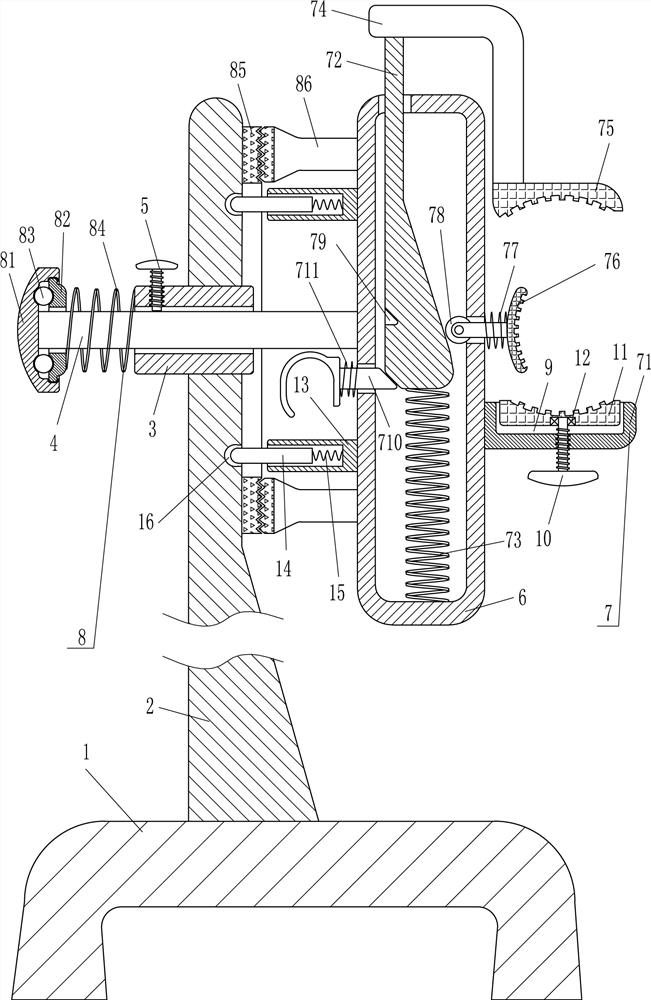
[0020] A multi-angle adjustable clamping machine for pipeline installation, please refer to figure 1 , including a base 1, a support plate 2, a shaft sleeve 3, a movable rod 4, a fastening bolt 5, a hollow tube 6 and a clamping mechanism 7, a support plate 2 is installed on the top of the base 1, and a shaft is embedded in the upper part of the support plate 2 Sleeve 3, the movable rod 4 is arranged in the shaft sleeve 3, the fastening bolt 5 matched with the movable rod 4 is arranged on the left side of the shaft sleeve 3, the hollow tube 6 is installed on the right end of the movable rod 4, and the hollow tube 6 is provided on the right Clamping mechanism 7.

[0021] The clamping mechanism 7 includes a fixed splint 71, a wedge block 72, a first spring 73, an L-shaped bar 74, a movable splint 75, a push rod 76, a second spring 77, a guide wheel 78, a clamp bar 710 and a third spring 711, The lower part of the outer right side of the hollow tube 6 is equipped with a fixed spl...

Embodiment 2

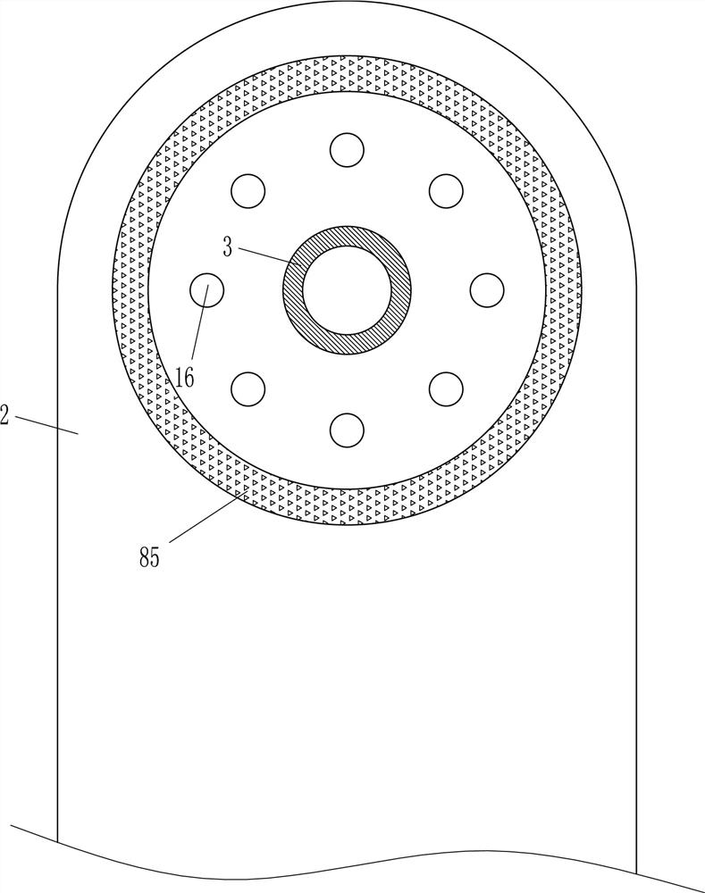
[0025] On the basis of Example 1, please refer to figure 1 and figure 2 , also includes clamping device 8, and clamping device 8 comprises circular groove plate 81, annular plate 82, ball 83, the 4th spring 84, annular friction plate 85 and friction bar 86, movable rod 4 left ends are fixedly connected with circle Shape groove plate 81, circular groove plate 81 inner movable type is provided with annular plate 82, and movable bar 4 passes through annular plate 82, and evenly spaced between annular plate 82 left side and circular groove plate 81 inner left side is provided with The ball 83, the fourth spring 84 is connected between the right side of the annular plate 82 and the left side of the shaft sleeve 3, the fourth spring 84 is wound on the movable rod 4, and an annular friction plate 85 is installed on the upper right side of the support plate 2, The upper and lower sides of the outer left side of the hollow tube 6 are equipped with friction rods 86, and the left end o...

Embodiment 3

[0028] On the basis of Example 2, please refer to figure 1 , also includes screw rod 10, movable block 11 and bearing 12, has groove 9 on the upper part of fixed splint 71, is provided with movable block 11 slidingly in groove 9, and bearing 12 is embedded in the bottom of movable block 11, and fixed splint 71 The lower part is screwed with a screw rod 10, and the top of the screw rod 10 is connected with the bearing 12 through an interference connection.

[0029] Also comprise sleeve 13, slide bar 14 and the 5th spring 15, both sides of hollow tube 6 outer left side surface are fixedly connected with sleeve 13, slide type is provided with slide bar 14 in sleeve 13, slide bar 14 right-hand sides A fifth spring 15 is connected with the sleeve 13 , and eight grooves 16 are evenly spaced on the upper right side of the support plate 2 , and the grooves 16 cooperate with the slide bar 14 .

[0030] The working process of this device is as follows: When the PVC pipe is fixed, if th...


PUM


Abstract

The invention relates to a pipe clamping machine, and particularly relates to a multi-angle adjustable pipe clamping machine for pipeline installation. The technical problem to be solved is to providea multi-angle adjustable pipe clamping machine for pipeline installation, capable of clamping a PVC pipe, facilitating to adjusting the angle of the PVC pipe, completing the installation only by oneconstructor, and rapidly clamping and detaching the PVC pipe. The multi-angle adjustable pipe clamping machine for the pipeline installation comprises a base, a support plate, a shaft sleeve and the like, wherein a support plate is installed at the top of the base, and the shaft sleeve is installed on the upper part of the support plate in an embedded manner. According to the multi-angle adjustable pipe clamping machine for the pipeline installation, a hollow pipe can be rotated through the cooperation of a fastening bolt and a movable rod, so that the PVC pipe on the hollow pipe can be drivento rotate, and then the angle of the PVC pipe can be adjusted; and a movable clamping plate can be rapidly driven to clamp downwards the PVC pipe or release upwards the PVC pipe through the cooperation of a guide wheel and a wedge-shaped block, and in this way, the PVC pipe can be rapidly clamped and detached.

Description

technical field [0001] The invention relates to a pipe clamping machine, in particular to a multi-angle adjustable pipe clamping machine for pipeline installation. Background technique [0002] A pipeline is a device connected by pipes, pipe connectors and valves to transport gas, liquid or fluid with solid particles. Usually, after the fluid is pressurized by a blower, compressor, pump and boiler, the high pressure from the pipeline It can also be transported by the pressure or gravity of the fluid itself. The pipeline is widely used, mainly in water supply, drainage, heat supply, gas supply, long-distance transportation of oil and natural gas, agricultural irrigation, hydraulic engineering and various in industrial installations. [0003] When installing PVC pipes, since the installation site is not necessarily horizontal and vertical, when installing PVC pipes in various complicated places, it is necessary to adjust the various angles of the PVC pipes before proceeding t...

Claims


Application Information

Patent Timeline
Patent Type & Authority Patents(China)
IPC IPC(8): B25B11/02
CPCB25B11/02
Inventor 黄东平林绍杰吴用存
Owner 海南红塔卷烟有限责任公司
Features
  • R&D
  • Intellectual Property
  • Life Sciences
  • Materials
  • Tech Scout
  • Unparalleled Data Quality
  • Higher Quality Content
  • 60% Fewer Hallucinations
Learn More