Front partition plate lower mounting plate and cross beam assembly

A front bulkhead and mounting plate technology, which is applied to vehicle components, transportation and packaging, and upper structures, can solve problems that affect assembly efficiency, excessively long dimensional chains, and inability to ensure connection strength, and achieve faster assembly efficiency and dimensional chains. The effect of less and simple structure

Pending Publication Date: 2019-11-19
SAIC-GM-WULING AUTOMOBILE CO LTD
View PDF0 Cites 2 Cited by
  • Summary
  • Abstract
  • Description
  • Claims
  • Application Information

AI Technical Summary

Problems solved by technology

[0003] 1. If figure 1 , Figure 1a and Figure 1b As shown, the connection structure between the passenger car engine compartment and the lower mounting plate of the front bulkhead includes the dash panel 1', the left front wheel cover 2', the right front wheel cover 5' and the lower mounting plate of the front bulkhead 3' the front bulkhead The lower mounting plate, the left front wheel house 2' and the right front wheel house 5' are respectively fixed at the bottom of the left and right ends of the lower mounting plate 3' of the front bulkhead, and the dash panel 1' is fixed under the front bulkhead On the front side of the mounting plate 3', the mounting plate under the front bulkhead is not reinforced by a beam, so the connection strength cannot be guaranteed;
[0004] 2. If figure 2 , Figure 2a and Figure 2b As shown, the connecting structure of another passenger car engine compartment to the lower mounting plate of the front bulkhead includes a dash panel 1", a left front wheel house 2", a right front wheel house 5" and a front bulkhead lower mounting plate 3". The lower mounting plate of the bulkhead, the left front wheel house 2″ and the right front wheel house 5″ are respectively fixed on the left and right bottoms of the lower mounting plate 3″ of the front bulkhead, and the dash panel 1′ is fixed on the front bulkhead On the front side of the lower mounting plate 3", a crossbeam 4" is arranged between the lower mounting plate 3" of the front bulkhead and the dash panel 1", and the left and right ends of the crossbeam 4" are connected with the left front wheel house 2" and the left front wheel house respectively. Right front wheel house 5 " is fixedly connected, and like this, be provided with crossbeam 4 " between front bulkhead mounting plate 3 " and dash panel 1 " and left front wheel house 2 " and right front wheel house 5 ", crossbeam 4 " "Set between the lower mounting plate 3" of the dash panel, the dash panel 1" and the left and right wheel covers 2", the crossbeam 4" needs to be connected with the lower mounting plate 3" of the dash panel, the dash panel, the left wheel cover 2" and the right wheel 4 parts including cover 5″ are matched, and the dimensional chain is too long, which leads to the accumulation of manufacturing tolerances and superimposed out-of-tolerance problems, which affects assembly efficiency

Method used


Image

  • Front partition plate lower mounting plate and cross beam assembly
  • Front partition plate lower mounting plate and cross beam assembly
  • Front partition plate lower mounting plate and cross beam assembly

Examples


Embodiment Construction

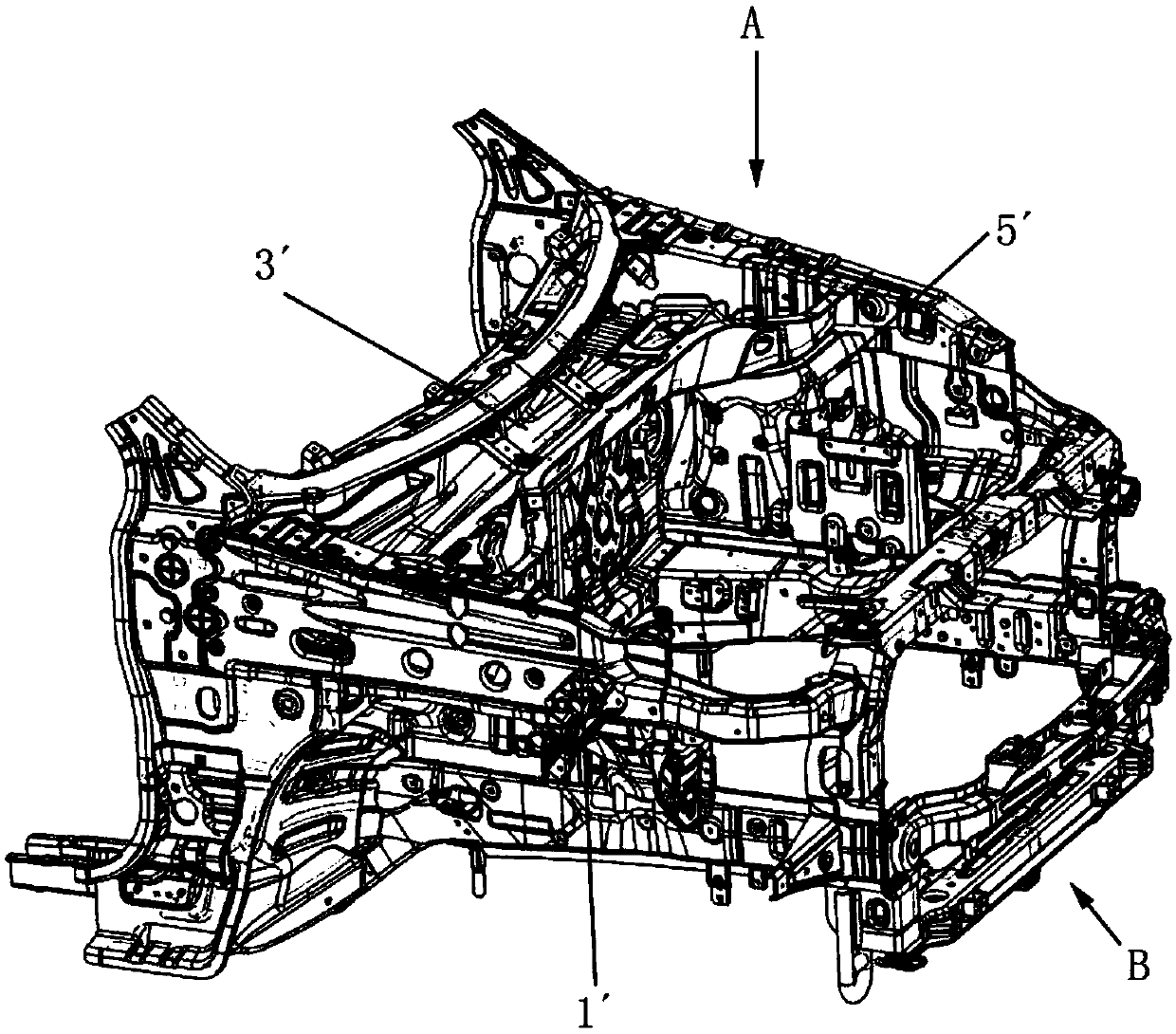
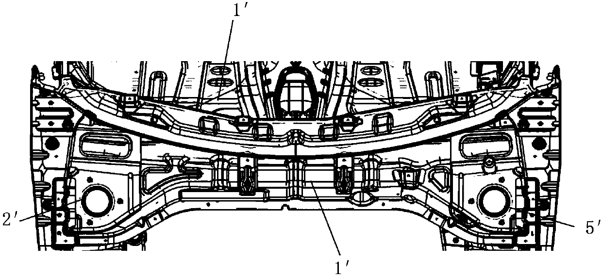
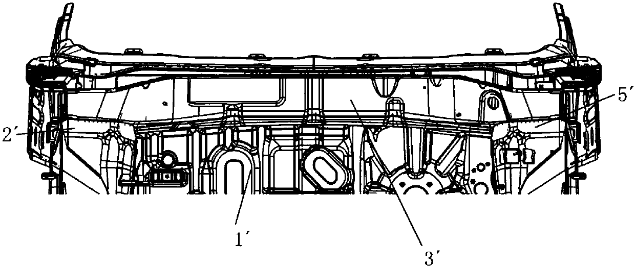
[0038] The following with attached Figure 3 to Figure 9 A crossbeam assembly of the lower mounting panel of the front bulkhead of the present invention is further described in detail.

[0039] A crossbeam assembly of the lower mounting plate of the dash panel of the present invention, please refer to Figure 3 to Figure 9 As shown, it includes a front bulkhead lower mounting plate 1 and a cross beam 2. The front bulkhead lower mounting plate 1 includes a bulkhead horizontal wall 10, a first vertical wall 11 and a second vertical wall 12. The first vertical wall The straight wall 11 and the second vertical wall 12 extend horizontally upward and are respectively fixed on the front and rear sides of the horizontal wall 10 of the partition, and the beam 2 is fixed horizontally on the front side of the upper surface of the horizontal wall 10 of the partition. A dash panel 3 is fixed to the rear end of the second vertical wall 12 . Specifically, the crossbeam 2 is installed on th...


PUM


Abstract

The invention discloses a front partition plate lower mounting plate and cross beam assembly, which comprises a front partition plate lower mounting plate and a cross beam. The front partition plate lower mounting plate comprises a partition plate horizontal wall, a first vertical wall and a second vertical wall; the first vertical wall and the second vertical wall horizontally extend upwards to be fixed to the front side and the rear side of the partition plate horizontal wall correspondingly; and the cross beam is horizontally fixed to the front side of the upper surface of the partition plate horizontal wall, and a front hoarding is fixed to the rear end of the second vertical wall. According to the front partition plate lower mounting plate and cross beam assembly, the overall rigidityof a front partition plate lower mounting part is effectively improved, the overall torsional rigidity of an engine cabin is increased, thus the overall torsional rigidity of an engine in the Y direction is increased to from 15415 Nm to 16503 Nm, and the torsional rigidity is increased by about 7%.

Description

technical field [0001] The invention relates to a crossbeam assembly of a lower mounting plate of a front bulkhead, in particular to a crossbeam assembly of a lower mounting plate of a front bulkhead which improves the overall rigidity of the mounting parts under a front bulkhead. Background technique [0002] There are the following two structures in the connection structure between the engine compartment of a traditional passenger car and the mounting plate under the front bulkhead: [0003] 1. If figure 1 , Figure 1a and Figure 1b As shown, the connection structure between the passenger car engine compartment and the lower mounting plate of the front bulkhead includes the dash panel 1', the left front wheel cover 2', the right front wheel cover 5' and the lower mounting plate of the front bulkhead 3' the front bulkhead The lower mounting plate, the left front wheel house 2' and the right front wheel house 5' are respectively fixed at the bottom of the left and right ...

Claims


Application Information

Patent Timeline
Patent Type & Authority Applications(China)
IPC IPC(8): B62D25/08B62D25/02B62D25/16
CPCB62D25/02B62D25/08B62D25/16
Inventor 杨昌文徐升陈聪侯明亮郭斌
Owner SAIC-GM-WULING AUTOMOBILE CO LTD
Why Eureka
Try Eureka