Sliding type installation method and system for offshore electric platform

An installation method and installation system technology, which are applied in the field of offshore wind power development and marine engineering, can solve the problems of large draught, unsuitable installation, and high design cycle for large floating crane transport barges, and achieve significant engineering economic benefits, wide application range, and choice. face widening effect

Active Publication Date: 2019-11-19
POWERCHINA HUADONG ENG COPORATION LTD
View PDF9 Cites 18 Cited by
  • Summary
  • Abstract
  • Description
  • Claims
  • Application Information

AI Technical Summary

Problems solved by technology

[0003] 1) Large-scale floating crane transport barges have a large draft, and there is a risk of bottoming out in small water depths, which cannot be applied to offshore platform installations in tidal flats or extremely shallow waters;
[0004] 2) At present, the maximum lifting weight of most floating crane transport barges in the world does not exceed 10,000 tons, which cannot meet the hoisting safety requirements of super large oil and gas platforms and offshore converter stations and other offshore platforms with a capacity of more than 10,000 tons;
[0005] 3) The current floating crane resources and window period are very tight to the demand of the project to be built, which cannot meet the construction period and economic requirements of large-scale marine development
In terms of installation technology of offshore electrical platforms: In the case of the above 1), the pr...

Method used


Image

  • Sliding type installation method and system for offshore electric platform
  • Sliding type installation method and system for offshore electric platform
  • Sliding type installation method and system for offshore electric platform

Examples


Embodiment Construction

[0044] In order to further illustrate the content, characteristics and effects of the present invention, an example of an offshore electrical platform with a lower block as a jacket, an upper block of 3,000 tons, and a water depth of about 4 m is listed hereby, and the description is as follows in conjunction with the accompanying drawings:

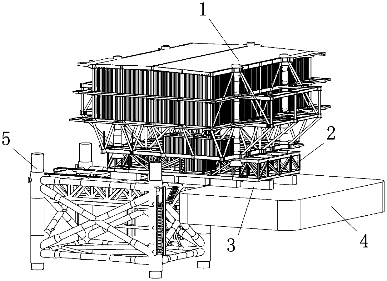
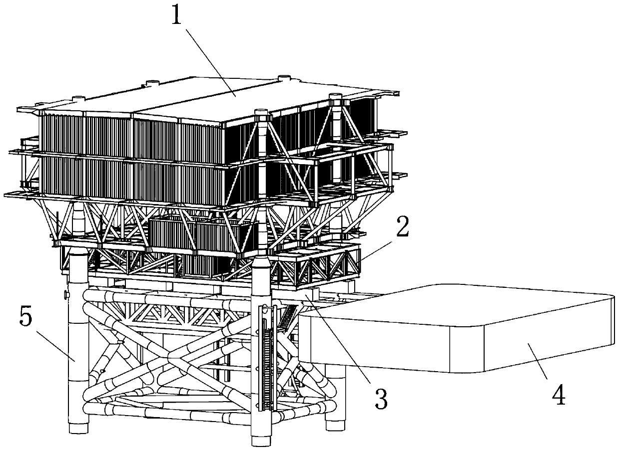
[0045] (1) if Figure 1~2 As shown, this embodiment is composed of the following contents: 1-3000 ton class offshore electrical platform upper block, 2-double-layer support truss, 3-SPMT vehicle group, 4-transport barge, 5-jacket. The upper module 1 is constructed at the dock base, and is temporarily supported by a double-layer support truss 2, and the lower part of the double-layer support truss 2 is supported on the horizontal bracket of the SPMT vehicle group 3. The upper block 1 and the double-layer support truss 2 slide together from the construction site by the SPMT vehicle group 3 to the transport barge 4, and the transport barge 4...


PUM


Abstract

The invention belongs to the field of ocean engineering, particularly belongs to the field of offshore wind power development, and particularly relates to sliding type installation method and system for an offshore electric platform. The sliding type installation method and the system for the offshore electric platform have the following beneficial effects that (1) the application range is wide, ultra-large type ocean platforms at very shallow water depth can be installed, the limitation requirements on a transportation barge, an upper module and a lower module are less besides the necessary support structure bearing capacity requirement, a classic structure style and a layout plan of the platform do not need to be changed, the selecting surface for engineering optimization is widened, andthe construction period and the work amount can be effectively controlled; (2) the butt joint of the upper module and the lower module of the offshore platform can be operated stably, accurately andcontrollably with the help of a track and a self-propelled modular trailer (SPMT) set, the problems of collision and inclination probably occurred in a hoisting method or a floating-supporting methodare avoided, and a butt-joint buffer device at a pile connecting part has no need to be arranged; and (3) various steps are conveniently constructed and simply operated, and the remarkable engineeringeconomic benefit is achieved.

Description

technical field [0001] The invention belongs to the field of marine engineering, in particular to the field of offshore wind power development, and in particular relates to a sliding installation method and system for an offshore electrical platform. Background technique [0002] With the deepening of ocean development, more and more offshore platforms are put into use. In most engineering projects, the installation process of the platform is one of the decisive factors that determine the economics of the project, and it also has an important impact on the structural type. The conventional installation method of the offshore platform is to use the floating crane transport barge to hoist the upper module and place it on the pre-constructed lower foundation structure (such as jacket, high pile cap, etc.), the related technology is relatively mature, but the hoisting method The application has the following limitations: [0003] 1) Large-scale floating crane transport barges ...

Claims


Application Information

Patent Timeline
IPC IPC(8): E02B17/00
CPCE02B17/00E02B2017/0043E02B2017/0047
Inventor 孙震洲孙杏建汤群益俞华锋姜贞强袁建平王淡善王永发吕国儿何小花吴吉光陶安於刚节李天昊
Owner POWERCHINA HUADONG ENG COPORATION LTD
Why Eureka
Try Eureka