A pneumatic axial flow emergency shut-off valve

An axial flow, shut-off valve technology, applied in the direction of sliding valve, balance valve, valve device, etc., can solve the problems of obstructing gas flow and flow, weak flow capacity, unable to work normally, etc., to prevent bending deformation and reduce flow Resistance, easy maintenance effect

Active Publication Date: 2021-03-02
TIANJIN BTER FLUID CONTROL VALVE +2
View PDF9 Cites 0 Cited by
  • Summary
  • Abstract
  • Description
  • Claims
  • Application Information

AI Technical Summary

Problems solved by technology

At present, the structure most used in the pneumatic axial flow emergency shut-off valve market is the swing type pneumatic axial flow emergency shut-off valve, whose switch is controlled by a mechanical pilot, and the sealing flap connecting plate is connected with the hook in the pilot , when the hook is disengaged, the sealing flap on the valve body will turn downwards under the action of its own weight and the force of the plane scroll spring to contact and seal with the valve seat after losing the external force, and cut off the passage in the valve body. This structure It is better to use on small-diameter valves, but it shows obvious shortcomings when used on large-diameter valves. The biggest disadvantage is that due to the increase in valve diameter, the sealing flap also needs to be enlarged, and the pressure increases, and the sealing flap also needs to be thickened. In this way, the sealing flap will be very large and heavy. When the valve is closed, the sealing flap will have a considerable impact on the valve seat under the action of its own weight and the force of the plane scroll spring, resulting in damage to the sealing surface and sealing elements. At the same time, Because the force of the impact is quite large, it will also cause damage to other equipment in the entire gas pipeline, which is not conducive to the safety of the gas transmission equipment and the entire pipeline, so it is not suitable to use a swing-type pneumatic axial flow emergency shut-off valve on a large-diameter pipeline; Several other forms of pneumatic axial flow emergency shut-off valves are mostly butterfly valves, globe valves, ball valves, etc. The shortcoming of the valve is that the closing speed is relatively slow and the flow capacity is relatively weak. Although the closing speed of the butterfly valve type emergency shut-off valve is faster than that of the globe valve type and the ball valve type, after the butterfly valve type is opened, the valve plate is in the middle of the valve body and There is a certain angle, which hinders the flow and velocity of the gas to a certain extent, and also produces impact vortex. Although the opening speed of the stop valve can also be accelerated, its flow channel is Z-shaped, which is not conducive to the flow of gas, so it is not conducive to the safety of the equipment. Safety
[0003] At present, there are two types of pneumatic axial-flow emergency cut-off cylinders: diaphragm type and piston type, but most of them are double-acting cylinders controlled by air pressure. The performance of the cylinder is slow, stable, and low frequency. The closed valve will not be satisfied. The pneumatic control system is generally a mechanical or electronic structure. The closing response time of the mechanical structure is longer, and the closing response time of the electronic structure is shorter, but it will not work normally due to power failure, affecting normal transportation.

Method used


Image

  • A pneumatic axial flow emergency shut-off valve
  • A pneumatic axial flow emergency shut-off valve
  • A pneumatic axial flow emergency shut-off valve

Examples


Embodiment Construction

[0030] The present invention will be described in further detail below in conjunction with the accompanying drawings.

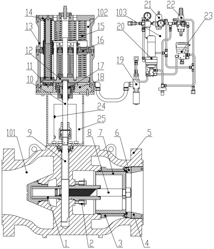
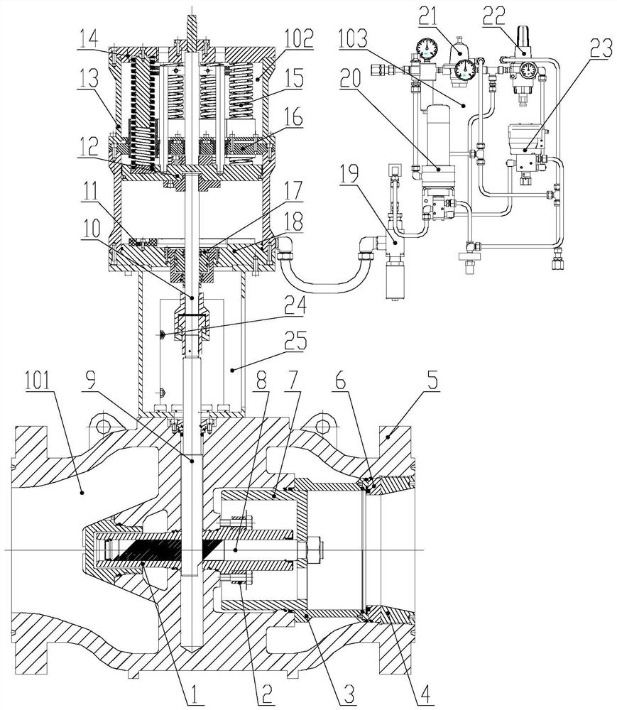
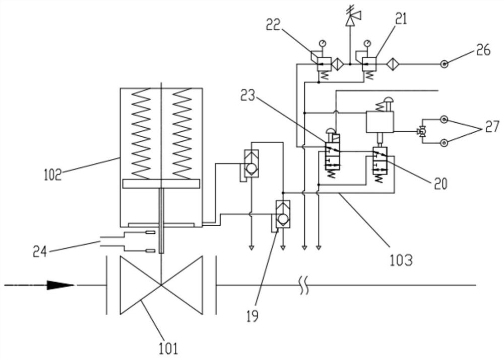
[0031]With reference to the accompanying drawings, a pneumatic axial flow emergency shut-off valve includes a guide sleeve 1, a gland 2, a support sleeve 3, a stop sleeve 4, a valve body 5, a sealing seat 6, a piston body 7, a piston rod 8, and a valve stem 9. Output shaft 10, buffer pad 11, piston 12, cylinder body 13, upper cylinder head 14, spring 15, guide plate 16, buffer device 17, lower cylinder head 18, quick discharge valve 19, pilot 20, pressure reducing valve 21. Filter decompression valve 22, electromagnetic valve 23. The guide sleeve 1 is fixed on the valve body 5 by the gland 2, the piston rod 8 passes through the piston body 7 and is fixed with a nut, the piston body 7 moves in the support sleeve 3 to control the valve switch, the support sleeve 3 and the seal The seat 6 is fixed on the valve body 5 through the connecting thread of the stop sl...


PUM


Abstract

The invention relates to a pneumatic axial flow type emergency cutoff valve. An air cylinder assembly, a pneumatic control system and an axial flow type valve assembly are included. The air cylinder assembly and the axial flow type valve assembly are connected. The pneumatic control system controls the air cylinder assembly to act. The air cylinder assembly is a multi-spring energy accumulation type single-acting air cylinder. The pneumatic control system receives gas signals and power signals. The axial flow type valve assembly is of an axial flow type circulation channel structure. In the normal work state, a gas source is input into the air cylinder assembly through a passage, the air cylinder assembly drives the axial flow type valve assembly to move, and when the pressure is abnormalor power failures happen, through changing of the gas signals and the power signals, a control gas path is changed, gas in the air cylinder assembly is rapidly discharged, the valve is rapidly closed,passages on the upstream and downstream parts of a pipeline are cut off, and safety of downstream equipment is protected. According to the pneumatic axial flow type emergency cutoff valve, control isconducted through the gas signals and the power signals, rapid closing of the valve can be achieved, media can rapidly pass through the axial flow type channel, multiple springs have the function ofenergy accumulating, actions are rapid, space can be saved as well, the structure is simple, and maintaining is convenient.

Description

technical field [0001] The invention relates to the technical field of pneumatic axial-flow emergency shut-off equipment, in particular to a pneumatic axial-flow emergency shut-off valve. Background technique [0002] The pressure control system of the natural gas transmission station is mainly composed of a pneumatic axial flow emergency shut-off valve, a monitoring pressure regulating valve and a working regulating valve. Connection, the pilot (pilot valve) on the valve body controls the opening and closing of the pneumatic axial flow emergency shut-off valve by receiving the downstream feedback pressure, and sets the downstream pressure within the control range to ensure the normal downstream pipeline air supply pressure and safe delivery of gas. At present, the structure most used in the pneumatic axial flow emergency shut-off valve market is the swing type pneumatic axial flow emergency shut-off valve, whose switch is controlled by a mechanical pilot, and the sealing f...

Claims


Application Information

Patent Timeline
Patent Type & Authority Patents(China)
IPC IPC(8): F16K3/24F16K3/314F16K3/316F16K3/30F16K17/00F16K27/04F16K31/122F16K31/143F16K37/00
CPCF16K3/24F16K3/30F16K3/314F16K3/316F16K17/00F16K27/041F16K31/1221F16K31/143F16K37/0083
Inventor 李东明黄健民刘维洲王贝贝周新民赵伟李翔黄楠石杰南海军刘大伟
Owner TIANJIN BTER FLUID CONTROL VALVE
Why Eureka
Try Eureka