
Anti-sidewise-bending deformation control device of H-shaped steel component and welding method

A technology of deformation control and H-shaped steel, which is applied in welding equipment, welding equipment, auxiliary equipment, etc., can solve the problems of difficult control and tediousness, achieve the effect of not easy to deform and bend, reduce frictional resistance, and ensure structural strength and stability

Active Publication Date: 2019-08-09
浙江中南绿建科技集团有限公司
View PDF7 Cites 11 Cited by
  • Summary
  • Abstract
  • Description
  • Claims
  • Application Information

AI Technical Summary

Problems solved by technology

[0002] At present, the development of steel structure buildings is changing with each passing day. Industrial plants and high-rise civil buildings have successively applied steel structure systems, and the most common components in this type of structure are H-shaped components, because H-shaped components have better mechanical properties and the largest The amount of steel used is saved to a minimum, but in the production process, due to the high height of the web, in the process of welding with the flange plate, deformation caused by welding usually occurs, and side bending deformation is the most common A kind of deformation, but this deformation is quite cumbersome and difficult to control in the later correction process

Method used


Image

  • Anti-sidewise-bending deformation control device of H-shaped steel component and welding method
  • Anti-sidewise-bending deformation control device of H-shaped steel component and welding method
  • Anti-sidewise-bending deformation control device of H-shaped steel component and welding method

Examples


Embodiment Construction

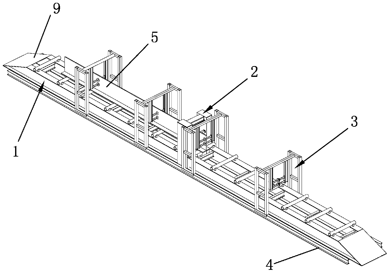
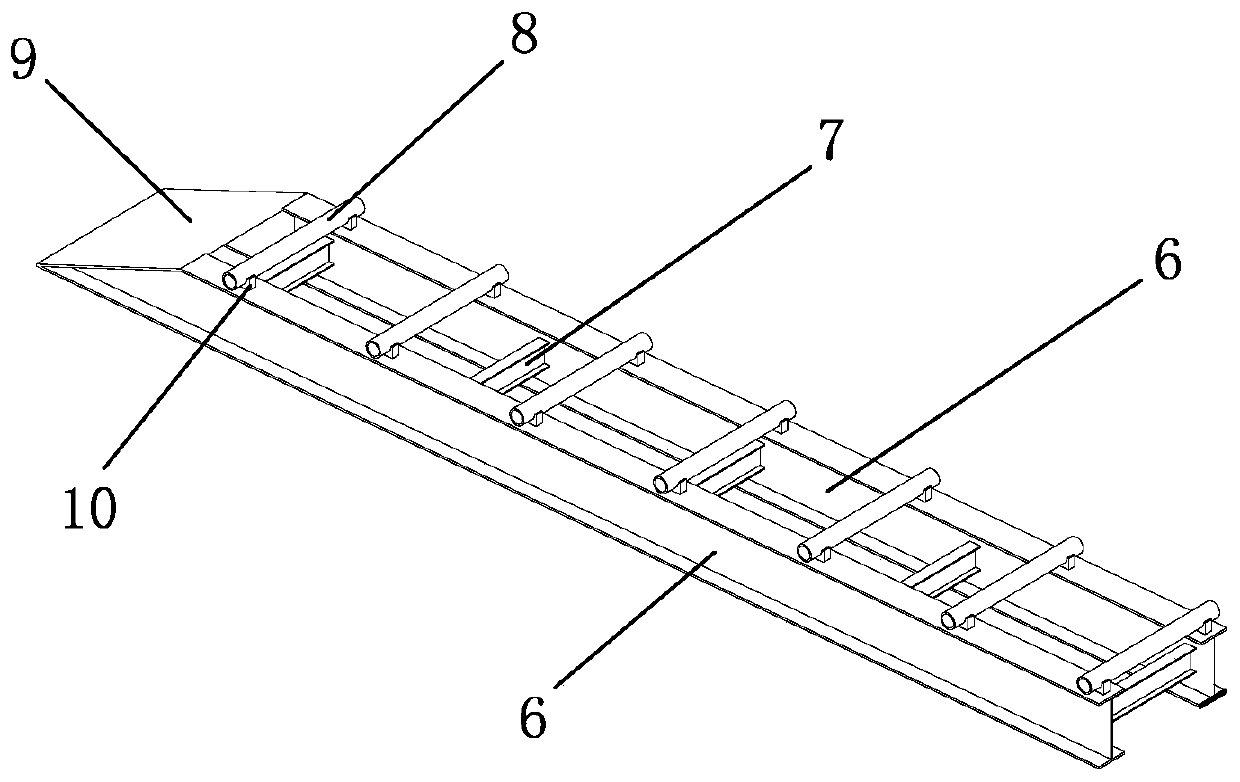
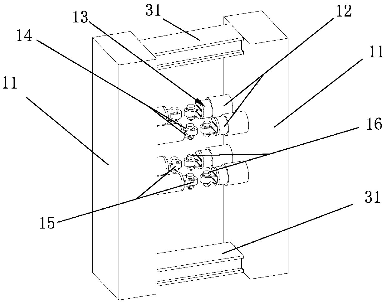
[0043] Such as Figure 1 to Figure 7 As shown, it is the H-shaped steel component anti-side bending deformation control device of the present invention, including the assembled tire frame 1, the anti-side bending device 2, the pressing device 3, the slide rail 4 and the member 5 to be welded, and the anti-side bending device 2 is located in the assembled tire In the middle of the frame 1, the left and right sides of the anti-bending device 2 are provided with an equal number of pressing devices 3, and the pressing devices 3 are distributed along the direction of assembling the tire frame 1, and the pressing devices 3 are located above the assembled tire frame 1 , the pressing device 3 is clamped on the slide rail 4, the slide rail 4 is symmetrically arranged on the front and rear sides of the assembled tire frame 1, the slide rail 4 is fixedly connected with the assembled tire frame 1, and the member 5 to be welded is located on the assembled tire frame 1.

[0044] The assembl...


PUM


Abstract

The invention discloses an anti-sidewise-bending deformation control device of an H-shaped steel component. The anti-sidewise-bending deformation control device comprises an assembly jig, an anti-sidewise-bending device, compression devices, a sliding rail and the to-be-welded component; the anti-sidewise-bending device is located in the middle of the assembly jig; the compression devices with thesame number are arranged on the left side and the right side of the anti-sidewise-bending device; and the compression devices are distributed in the direction of the assembly jig. A welding method comprises the steps: (1) the compression devices are adjusted; (2) a lower flange plate and a web are welded; and (3) an upper flange plate and the web are welded. During welding, the web at a welding point is compressed through the anti-sidewise-bending device, thus deformation and bending of the web in the welding process are avoided, two welding heads are symmetrically arranged on the welding positions of the flange plates and the web, the compression devices work to drive the to-be-welded component to move, the two sides of contact points of the web and the flange plates are synchronously welded through the two welding heads, in the process, the to-be-welded component can be semi-automatically welded, the machining efficiency of the H-shaped component can be improved, and the welding quality of the H-shaped component is guaranteed.

Description

technical field [0001] The invention relates to an H-shaped steel member anti-side bending deformation control device and a welding method thereof in the field of construction engineering. Background technique [0002] At present, the development of steel structure buildings is changing with each passing day. Industrial plants and high-rise civil buildings have successively applied steel structure systems, and the most common components in this type of structure are H-shaped components, because H-shaped components have better mechanical properties and the largest The amount of steel used is saved to a minimum, but in the production process, due to the high height of the web, in the process of welding with the flange plate, deformation caused by welding usually occurs, and side bending deformation is the most common A kind of deformation, but this deformation is quite cumbersome and difficult to control in the later correction process. Therefore, it is necessary to develop a...

Claims


Application Information

Patent Timeline
IPC IPC(8): B23K9/18B23K9/32B23K31/00B23K37/04B23K31/02
CPCB23K9/18B23K9/32B23K31/003B23K37/0443B23K31/022
Inventor 袁国平王杰蒋永扬李达汪炎胜史海军
Owner 浙江中南绿建科技集团有限公司
Learn More