
System and method for detecting time sequence of servo motor

A servo motor and timing technology, applied in the direction of measuring electrical variables, motor generator testing, measuring devices, etc., can solve the problems of increasing the economic cost of servo motors, increasing the complexity of servo motor testing, and complicated working steps of servo motors. Economical cost, effect of reducing cumbersomeness

Inactive Publication Date: 2019-11-19
SHANGHAI POWERMAX TECH INC
View PDF7 Cites 0 Cited by
  • Summary
  • Abstract
  • Description
  • Claims
  • Application Information

AI Technical Summary

Problems solved by technology

However, due to considerations such as industry competition, servo motor manufacturers generally do not disclose the driving parameters of servo motor drivers, so different servo motors require different servo motor drivers for adjustment and control, and it is difficult to unify the models of servo motor drivers to form A system for measuring the servo motor, which makes the working steps of the servo motor driver to drive the servo motor more complicated, increases the test complexity during the servo motor test process, and also increases the economic cost of the servo motor purchase

Method used


Image

  • System and method for detecting time sequence of servo motor
  • System and method for detecting time sequence of servo motor
  • System and method for detecting time sequence of servo motor

Examples


Embodiment Construction

[0037] The following will clearly and completely describe the technical solutions in the embodiments of the present invention with reference to the accompanying drawings in the embodiments of the present invention. Obviously, the described embodiments are only some, not all, embodiments of the present invention. Based on the embodiments of the present invention, all other embodiments obtained by persons of ordinary skill in the art without creative efforts fall within the protection scope of the present invention.

[0038] It should be noted that, in the case of no conflict, the embodiments of the present invention and the features in the embodiments can be combined with each other.

[0039] The present invention will be further described below in conjunction with the accompanying drawings and specific embodiments, but not as a limitation of the present invention.

[0040] A system for detecting the timing of servo motors in a preferred embodiment of the present invention has ...


PUM


Abstract

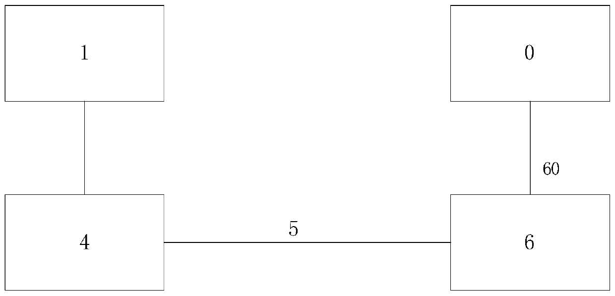
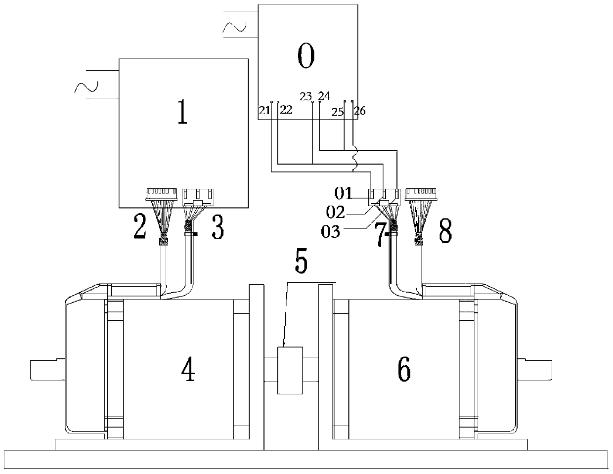
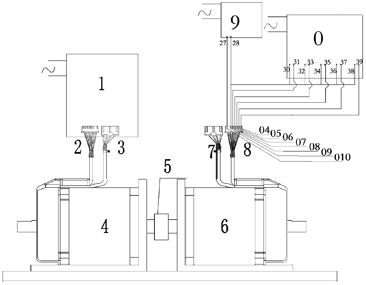
The invention discloses a system and method for detecting time sequence of a servo motor, and the system specifically comprises a first servo motor, a second servo motor and an oscilloscope, wherein the first servo motor is connected with the servo motor driver which is matched with the first servo motor in a time sequence and is preset with driving parameters, and the first servo motor is drivenby the servo motor driver to rotate; the second servo motor is connected with the motor of the first servo motor through a coupling shaft and rotates under the dragging of the first servo motor through the coaxial rotation of the coupling shaft and the first servo motor; and the oscilloscope is connected with the winding wire end and the encoder end of the second servo motor and is used for detecting the motor time sequence of the second servo motor. The beneficial effects of the above-mentioned technical scheme are that the first servo motor drags the second servo motor to rotate through thecoupling shaft, so that the working parameters of the motor can be directly measured by the oscilloscope, a corresponding servo motor driver does not need to be matched, the complexity of the operation process of the servo motor is reduced, and the economic cost of selecting the servo motor is reduced.

Description

technical field [0001] The invention relates to the control field of a servo motor, in particular to a system and method for detecting the timing sequence of a servo motor. Background technique [0002] There are a large number of servo motor manufacturers in the market today, and different servo motor manufacturers have different servo motor manufacturing processes, which leads to the inability to completely unify the timing of the servo motors. When operating the servo motor, the servo motor driver needs to match the timing of the servo motor. Unless it is a servo motor driver specially provided by the servo motor manufacturer to match the timing of the servo motor, other drivers cannot drive the servo motor. When selecting a servo motor, the timing of the servo motor can reflect the performance information of the servo motor. If the same driver is used to control the rotation of servo motors with different timings, various performances of different servo motors can be eas...

Claims


Application Information

Patent Timeline
IPC IPC(8): G01R31/34G01R13/00
CPCG01R13/00G01R31/34
Inventor 范美华
Owner SHANGHAI POWERMAX TECH INC
Learn More