Passive crystal oscillator sharing circuit

A passive crystal oscillator and crystal oscillator circuit technology, applied in the circuit field, can solve the problems of high cost, high processing cost, high material cost, and increased cost, and achieve the effects of saving space, reducing circuit cost, and reducing interference

Active Publication Date: 2019-11-19
AMOLOGIC (SHANGHAI) CO LTD
View PDF3 Cites 4 Cited by
  • Summary
  • Abstract
  • Description
  • Claims
  • Application Information

AI Technical Summary

Problems solved by technology

[0002] In a circuit board with multiple chips, in order to ensure the accuracy and reliability of information transmission between each chip, each chip needs a dedicated crystal oscillator to provide the same frequency clock signal, so each chip in the current technology Both need to set an independent crystal oscillator, resulting in an increase in cost
[0003] In order to solve the above problems, a 24M general-purpose crystal oscillator circuit is provided in the prior art, such as figure 1 As shown, more than two chips share one active crystal oscillator, and multiple chips share one active crystal oscillator through the strong driving capability of the active crystal oscillator. However, the above technical solution uses a relatively high-cost active crystal oscillator. Therefore the processing cost of prior art and material cost are higher

Method used


Image

  • Passive crystal oscillator sharing circuit
  • Passive crystal oscillator sharing circuit
  • Passive crystal oscillator sharing circuit

Examples


Embodiment Construction

[0069] The technical solutions in the embodiments of the present invention will be clearly and completely described below in conjunction with the accompanying drawings in the embodiments of the present invention. Obviously, the described embodiments are only a part of the embodiments of the present invention, rather than all the embodiments. Based on the embodiments of the present invention, all other embodiments obtained by those of ordinary skill in the art without creative work shall fall within the protection scope of the present invention.

[0070] It should be noted that the embodiments of the present invention and the features in the embodiments can be combined with each other if there is no conflict.

[0071] The present invention will be further described below with reference to the drawings and specific embodiments, but it is not a limitation of the present invention.

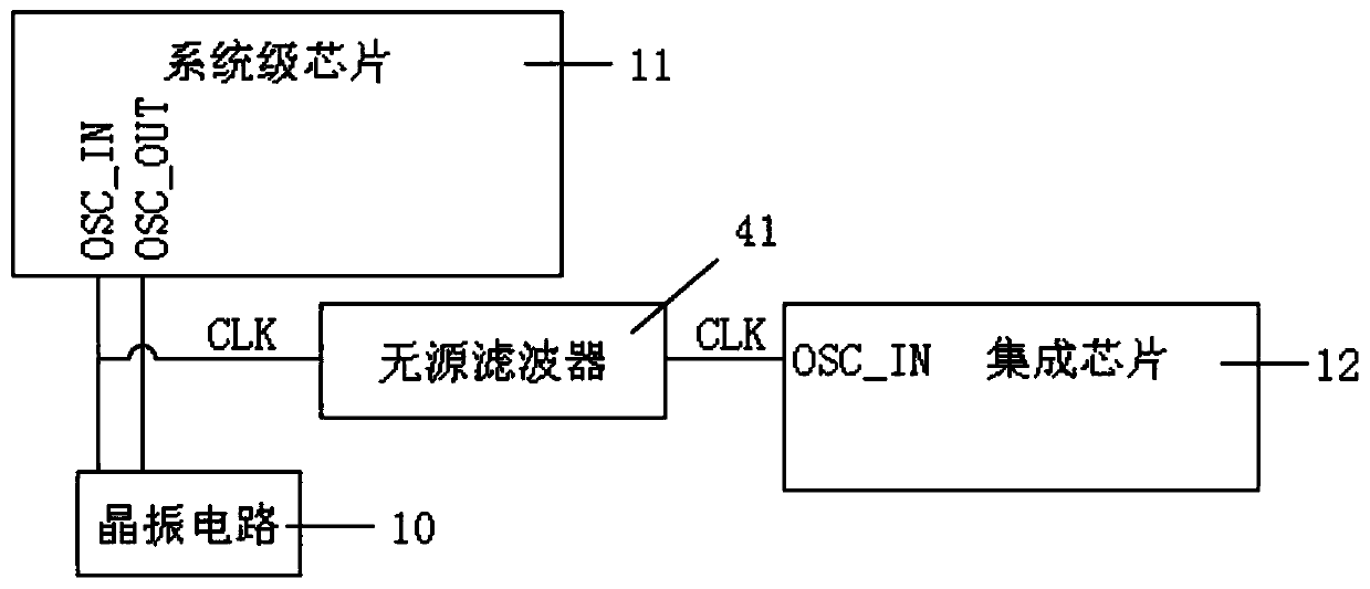
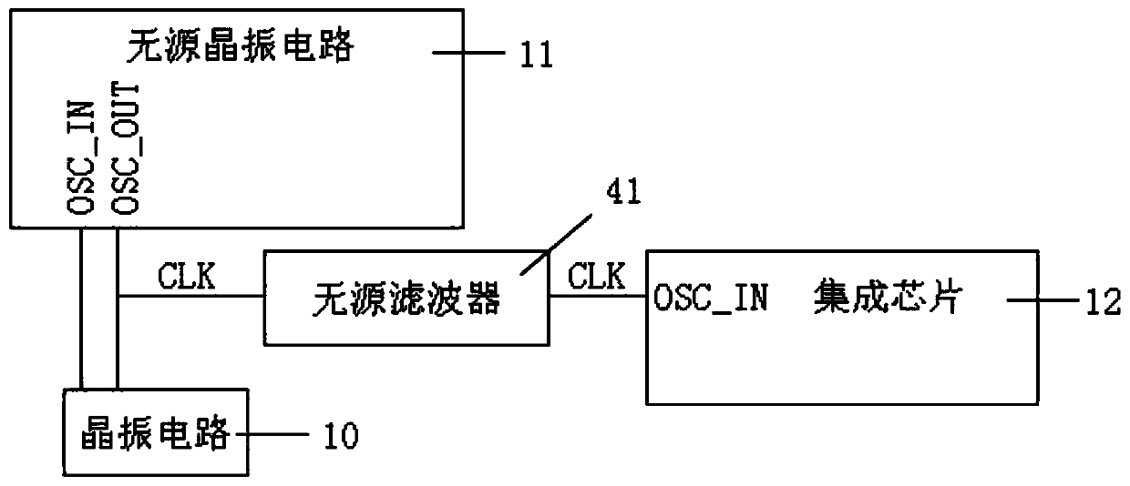
[0072] The present invention provides a passive crystal oscillator sharing circuit, such as Figure 2-3 S...


PUM


Abstract

The invention provides a passive crystal oscillator sharing circuit, which comprises a crystal oscillator circuit and a system-on-chip. The crystal oscillator circuit is used for outputting a clock signal. The crystal oscillator input pin and the crystal oscillator output pin of the system-on-chip are both connected with the crystal oscillator circuit and used for receiving clock signals and thenoutputting the clock signals. The crystal oscillator input pin of the integrated chip is selectively connected with one of the crystal oscillator input pin and the crystal oscillator output pin of thesystem-on-chip through the passive filter so as to receive a clock signal output by the system-on-chip. The passive filter reduces the interference, enables the frequencies of the clock signals of the system-on-chip and the integrated chip to be consistent, and reduces the number of crystal oscillators.

Description

Technical field [0001] The present invention relates to the technical field of circuits, in particular to a passive crystal oscillator sharing circuit. Background technique [0002] In a circuit board with multiple chips, in order to ensure the accuracy and reliability of the information transmission between each chip, each chip needs a special crystal oscillator to provide the same frequency clock signal, so each chip in the current technology Both need to set up an independent crystal oscillator, which leads to increased costs. [0003] In order to solve the above problems, the prior art provides a 24M universal crystal oscillator circuit, such as figure 1 As shown, that is, two or more chips share an active crystal oscillator, and through the strong driving ability of the active crystal oscillator, multiple chips share an active crystal oscillator. However, the above technical solution uses a higher cost active crystal oscillator. Therefore, the processing cost and material cos...

Claims


Application Information

Patent Timeline
Patent Type & Authority Applications(China)
IPC IPC(8): G06F1/12
CPCG06F1/12
Inventor 冯珑
Owner AMOLOGIC (SHANGHAI) CO LTD
Why Eureka
Try Eureka