Eureka AIR delivers breakthrough ideas for toughest innovation challenges, trusted by R&D personnel around the world.

Forest disaster monitoring method, device, equipment and system

A forest fire and fire technology, applied in the field of computer vision, can solve the problems of unsatisfactory effect and high labor cost, and achieve the effects of good monitoring effect, strong learning ability and labor cost saving

Inactive Publication Date: 2019-11-19
成都睿云物联科技有限公司
View PDF5 Cites 7 Cited by
  • Summary
  • Abstract
  • Description
  • Claims
  • Application Information

AI Technical Summary

Problems solved by technology

[0004] This application provides a forest fire monitoring method, device, equipment and system to solve the problems of unsatisfactory effects and high labor costs in the forest fire monitoring method in the related art

Method used


Image

  • Forest disaster monitoring method, device, equipment and system
  • Forest disaster monitoring method, device, equipment and system
  • Forest disaster monitoring method, device, equipment and system

Examples


Embodiment 1

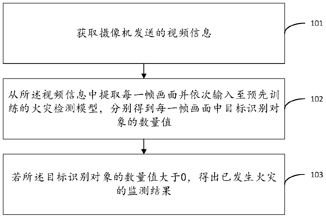
[0055] see figure 1 , figure 1It is a schematic flowchart of a forest fire monitoring method provided in the embodiment of the present application. like figure 1 As shown, the method includes the following steps:

[0056] S101: Obtain the video information sent by the camera; wherein, the camera is set up high in the forest to shoot the video information of the forest;

[0057] Specifically, similar to the traditional video surveillance and manual viewing methods, this embodiment also needs to first establish a complete video surveillance system in the forest, that is, a large number of cameras are set at the height of the forest by means of high platforms, towers or utility poles, etc., so that Make the monitoring area cover the entire forest area as much as possible. The video images captured by the camera can be transmitted to specific monitoring equipment through wired or wireless means for analysis and processing.

[0058] In some embodiments, the monitoring device c...

Embodiment 2

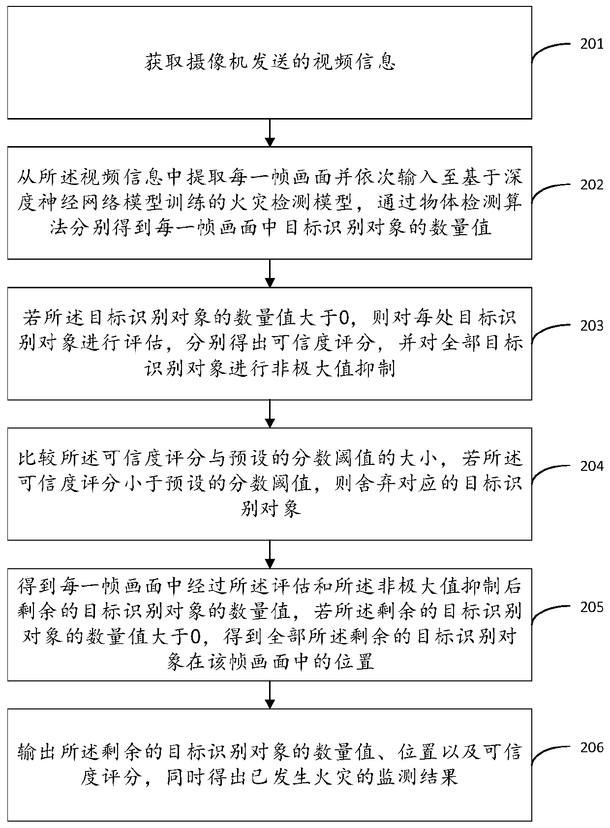
[0076] see figure 2 , figure 2 It is a schematic flowchart of another forest fire monitoring method provided in the embodiment of the present application. like figure 2 As shown, the method includes the following steps:

[0077] S201: Obtain video information sent by a camera; wherein, the camera is set high in the forest to capture the video information of the forest;

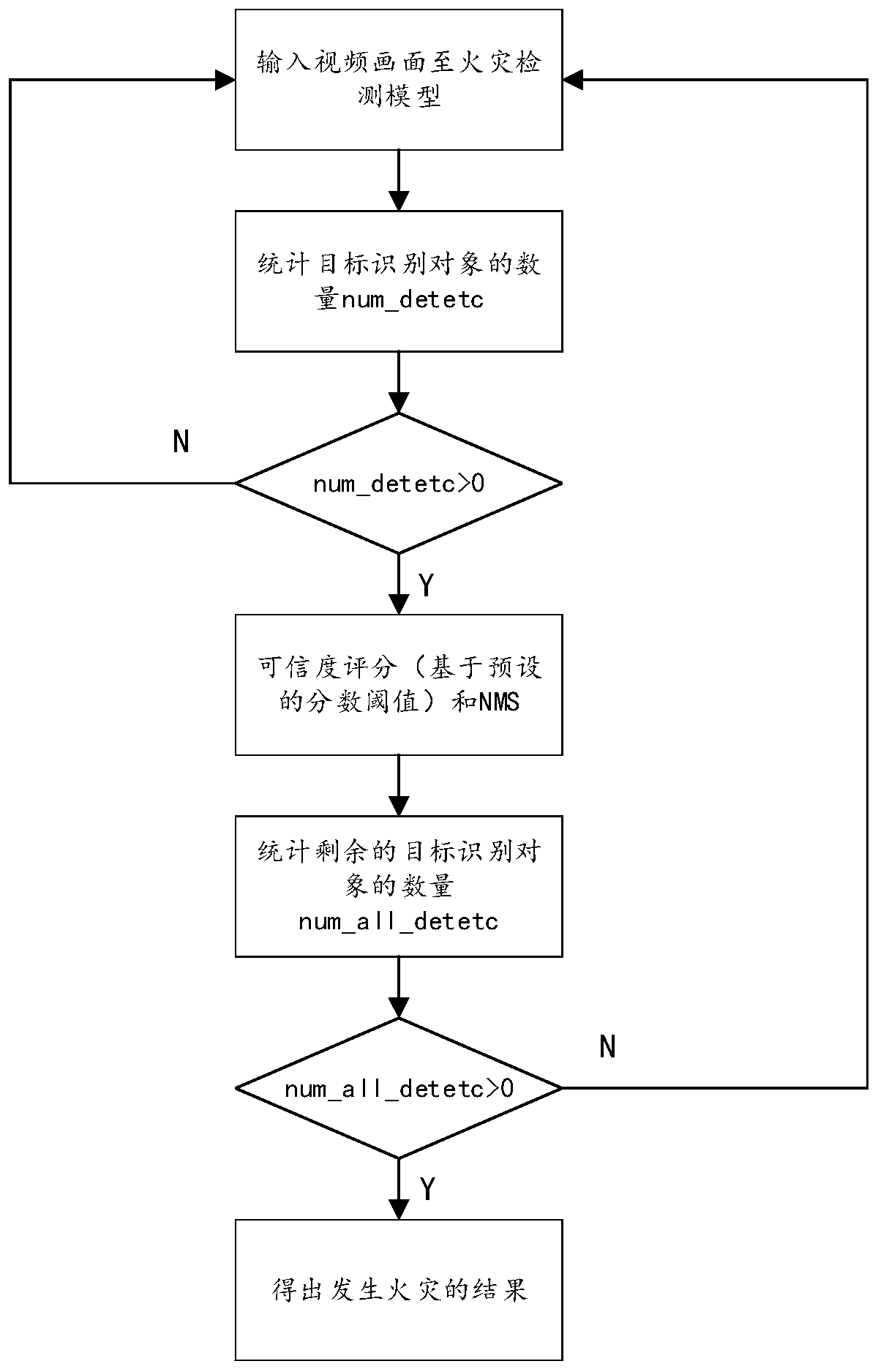
[0078] S202: Extract each frame of picture from the video information and sequentially input it to the fire detection model trained based on the deep neural network model, and obtain the quantity value of the target recognition object in each frame of picture through the object detection algorithm; wherein the target Recognition objects include target flame objects and target smoke objects;

[0079] S203: If the number of target recognition objects is greater than 0, evaluate each target recognition object to obtain a reliability score respectively, and perform non-maximum value suppression on all targe...


PUM


Abstract

The application relates to a forest disaster monitoring method, device, equipment and system. The method comprises the following steps: acquiring video information transmitted by a camera; extractingeach frame of picture from the video information, and inputting each frame of picture into a pre-trained fire disaster detection model to obtain the number value of target recognition objects in eachframe of picture, wherein the target recognition objects include target flame objects and target smoke objects; and if the number value of the target recognition objects is larger than 0, acquiring amonitoring result of an occurred fire disaster. Through the setting, a monitoring video picture is recognized with an artificial intelligence technology, so that the recognition result is sufficientlyaccurate as long as the sample quantity in the detection model is sufficient. Meanwhile, the detection process is carried out automatically without manual operation, so that the labor cost can be lowered on the premise of ensuring a good monitoring effect. Moreover, the objects are recognized through the combination of flame and smoke, so that the detection result is more reliable.

Description

technical field [0001] The present application relates to the technical field of computer vision, in particular to a forest fire monitoring method, device, equipment and system. Background technique [0002] Forest resources are very important natural resources in today's society, and once a forest fire breaks out, it will cause serious damage to the forest itself, other animal and plant resources in the forest, and the atmospheric environment. Therefore, all places attach great importance to forest fire prevention. However, no matter how perfect the forest fire prevention is, it is difficult to completely avoid the occurrence of forest fires. Therefore, it is important to detect fires in the forest at the first moment This is of great significance, so that the forest rangers can prevent the fire from spreading in time and put it out quickly, thereby protecting resources, the environment and personal safety, etc. [0003] Currently, fire monitoring in various situations inc...

Claims


Application Information

Patent Timeline
IPC IPC(8): G08B17/00G08B17/12
CPCG08B17/005G08B17/125
Inventor 张一邵泉铭
Owner 成都睿云物联科技有限公司
Why Eureka
Eureka Blog
Learn More