
Bending structure manufacturing method, bending structure and display panel

A manufacturing method and a technology for a display panel are applied in the field of a bending structure, a display panel, and a manufacturing method of the bending structure, which can solve the problems of fracture and low yield of the bending structure, and achieve the effect of improving the yield.

Active Publication Date: 2019-11-19
SHANGHAI TIANMA MICRO ELECTRONICS CO LTD
View PDF6 Cites 3 Cited by
  • Summary
  • Abstract
  • Description
  • Claims
  • Application Information

AI Technical Summary

Problems solved by technology

However, in the existing bending structure, the metal wiring layer will be stretched or even broken due to stress, resulting in a low yield of the existing bending structure.

Method used


Image

  • Bending structure manufacturing method, bending structure and display panel
  • Bending structure manufacturing method, bending structure and display panel
  • Bending structure manufacturing method, bending structure and display panel

Examples


Embodiment Construction

[0030] The present invention will be further described in detail below in conjunction with the accompanying drawings and embodiments. It should be understood that the specific embodiments described here are only used to explain the present invention, but not to limit the present invention. In addition, it should be noted that, for the convenience of description, only some structures related to the present invention are shown in the drawings but not all structures.

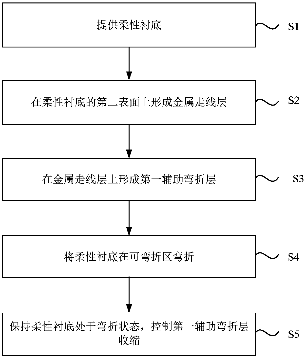
[0031] figure 1 It is a flowchart of a method for manufacturing a bent structure provided by an embodiment of the present invention. see figure 1 , the manufacturing method of the bent structure includes:

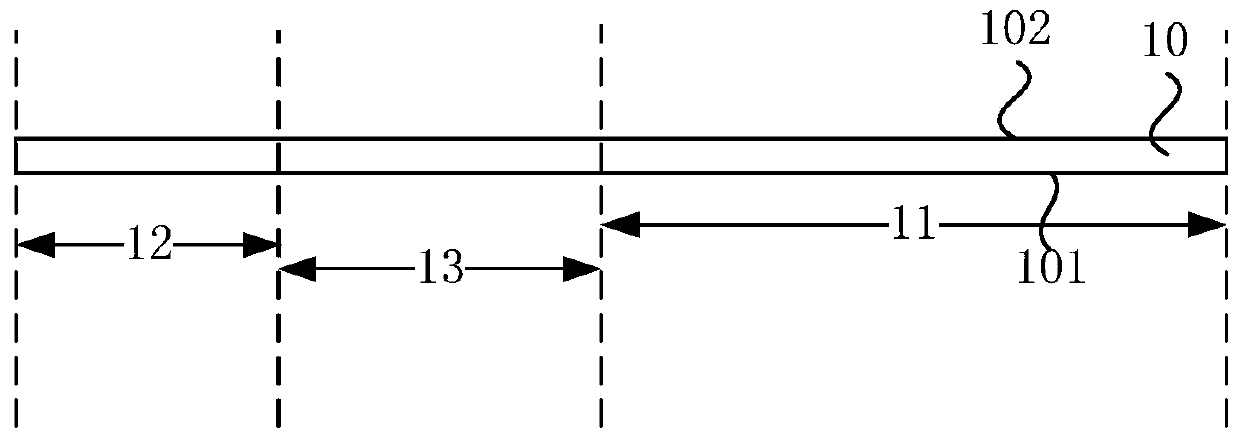
[0032] S1. A flexible substrate is provided. The flexible substrate includes a first non-bending region, a second non-bending region, and a bendable region connecting the first non-bending region and the second non-bending region; the flexible substrate further includes opposing first and second surfaces.

...


PUM


Abstract

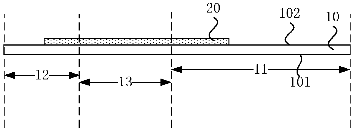
The embodiment of the invention discloses a bending structure manufacturing method, a bending structure and a display panel. The bending structure manufacturing method comprises the steps of providinga flexible substrate, wherein the flexible substrate comprises a first non-bending area, a second non-bending area, and a bendable area for connecting the first non-bending area and the second non-bending area; forming a metal routing layer on the second surface of the flexible substrate, wherein at least part of metal routing layer is located in the bendable area; forming a first auxiliary bending layer on the metal routing layer, wherein at least part of the first auxiliary bending layer covers the metal routing layer located in the bendable area, and the first auxiliary bending layer is made of a contractile memory material; bending the flexible substrate in the bendable area, so that the second non-bending area is located on one side, far away from the second surface, of the first surface of the first non-bending area; and keeping the flexible substrate to be at a bending state, and controlling the first auxiliary bending layer to contract, so that the area of the first auxiliarybending layer is reduced, and the manufacturing yield of the bending structure is improved.

Description

technical field [0001] Embodiments of the present invention relate to display technologies, and in particular, to a method for manufacturing a bent structure, a bent structure, and a display panel. Background technique [0002] As the size of mobile phone screens gradually increases, the screen-to-body ratio has become an important indicator for measuring the performance of mobile phones. The screen-to-body ratio refers to the ratio of the display area of ​​a mobile phone to the total screen area. On the one hand, a higher screen-to-body ratio makes the appearance of the mobile phone more beautiful, and on the other hand, it can bring users a better viewing experience. [0003] However, at present, a binding area is often set in the display panel of a mobile phone, and a plurality of connecting pins are arranged in the binding area, and the connecting pins are used to bind with other circuit components (such as a driver chip or a flexible circuit board, etc.) connected to ...

Claims


Application Information

Patent Timeline
Patent Type & Authority Applications(China)
IPC IPC(8): G09F9/30
CPCG09F9/301
Inventor 冷传利
Owner SHANGHAI TIANMA MICRO ELECTRONICS CO LTD
Learn More