
Ink fountain for building engineering

A construction engineering and ink fountain technology, which is applied in the field of ink fountains for construction engineering, can solve problems such as unfavorable use and reduction of ink fountains.

Inactive Publication Date: 2019-11-22
深圳市河图建设项目管理有限公司
View PDF1 Cites 4 Cited by
  • Summary
  • Abstract
  • Description
  • Claims
  • Application Information

AI Technical Summary

Problems solved by technology

An ink fountain in the above patent has the following disadvantages: after the ink thread has been used for a period of time, the ink on the cotton thread will be significantly reduced, which is not conducive to the use of the ink fountain

Method used


Image

  • Ink fountain for building engineering
  • Ink fountain for building engineering
  • Ink fountain for building engineering

Examples


Embodiment 1

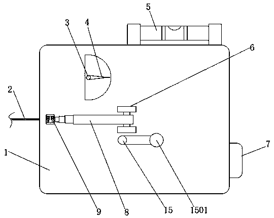
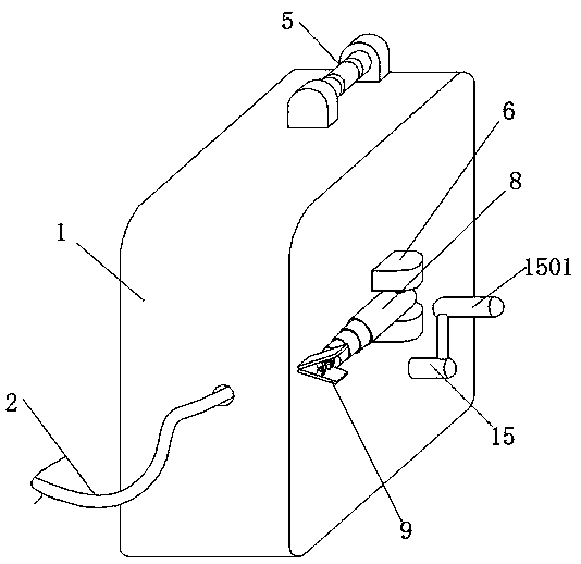
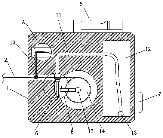
[0034] refer to Figure 1-7 , an ink fountain for construction engineering, comprising a main body 1, an ink tank 12 is provided on one side of the main body 1, and a first cavity is opened on the other side of the main body 1, and the main body 1 is rotatably connected at the inner wall of one side of the first cavity. There is a rotating shaft 15, and the middle part of the rotating shaft 15 is welded with a pulley 14, and the outside of the pulley 14 is wound with an ink line 2. The main body 1 has a first through hole on the inner wall of one side of the first cavity, and the ink line 2 is in the first through hole. extends to the outside of the main body 1, the main body 1 is provided with a second through hole between the first cavity and the ink tank 12, the main body 1 is provided with a cotton thread 11 at the second through hole, and one end of the cotton thread 11 is in the ink tank 12 Inside, the cotton thread 11 can absorb the ink in the ink tank 12 and send it to...

Embodiment 2

[0048] refer to Figure 8-10 , a kind of ink fountain for construction engineering. Compared with Embodiment 1, in order to increase the practicability of the device and prolong the service life of the device, the sponge 20 is provided with rubber pads 26 on both sides of the semicircular groove, and the ink line 2 When in use, it will rub against both sides of the semicircular groove of the sponge 20, especially when the ink line 2 is not parallel, and the rubber pad 26 can prevent the contact between the sponge 20 and the ink line 2, so that the service life of the sponge 20 will be increased .

[0049] When in use, the ink line 2 is pulled, the ink line 2 drives the pulley 14 to rotate, the pulley 14 drives the rotating shaft 15 to rotate, the rotating shaft 15 drives the rotating rod 23 to rotate around the rotating shaft 15, and the rotating rod 23 rotates once to hit the moving block 22 once. Make the moving block 22 move, the moving block 22 drives the push rod 16 to m...


PUM


Abstract

The invention belongs to the technical field of building equipment, in particular relates to an ink fountain for building engineering. Aiming at the problem that ink on cotton threads will be obviously reduced after ink lines are used for a period of time and is not beneficial to the use of ink fountain, the following scheme is proposed. The ink fountain for building engineering comprises a main body, wherein one side of the main body is provided with an ink bin, the other side of the main body is provided with a first cavity, the main body is rotatably connected with a rotating shaft at the inner wall of one side of the first cavity, a pulley is welded at the middle of the rotating shaft, and ink lines are wound outside the pulley. According to the invention, the ink line drives the rotating rod to rotate around the rotating shaft, the rotating rod rotates for one circle to hit the moving block once, the push rod moves at the same time, the spring is stretched, the push rod drives themoving block to extrude sponge, the ink in the sponge is absorbed by the ink line, the rotating rod rotates continuously, the ink line continuously absorbs ink during the extraction process, and meanwhile, the ink line is evenly soaked by the ink through the water absorption of the ink line, so that the ink line can be used for a long time.

Description

technical field [0001] The invention relates to the technical field of construction equipment, in particular to an ink fountain for construction engineering. Background technique [0002] In construction projects, the ink fountain is a commonly used measuring device, but the ink in the existing ink fountain is easy to spill. At the same time, after adding ink, the cotton thread has more ink when it is used for the first time, and after a period of use, the cotton thread The ink on the ink fountain will be significantly reduced, which is not conducive to the use of the ink fountain. [0003] After retrieval, the Chinese patent application number is 201820264786.1, which discloses an ink fountain, which includes an ink fountain body and a wire wheel. The wire wheel is installed in the ink fountain body through the rotation of the shaft. There are baffles, and the two baffles are respectively fixed on the two ends of the wire wheel. The ink fountain body is movably provided wi...

Claims


Application Information

Patent Timeline
Patent Type & Authority Applications(China)
IPC IPC(8): B25H7/04
CPCB25H7/04B25H7/045
Inventor 李超柳晓云柳泽滨张世杰陈俊君刘钦杰
Owner 深圳市河图建设项目管理有限公司
Learn More