A wire feeding drive mechanism and wire outlet machine
What is Al technical title?
Al technical title is built by PatSnap Al team. It summarizes the technical point description of the patent document.
A technology of driving mechanism and outlet machine, which is applied in the direction of conveying filamentous materials, thin material processing, transportation and packaging, etc., and can solve problems such as broken wires, winding, messy wires, etc.
Active Publication Date: 2021-06-04
青岛昊川电子科技有限公司
View PDF8 Cites 0 Cited by
Summary
Abstract
Description
Claims
Application Information
AI Technical Summary
This helps you quickly interpret patents by identifying the three key elements:
Problems solved by technology
Method used
Benefits of technology
Problems solved by technology
[0004] The invention provides a wire feeding drive mechanism, which is used to solve the problems of messy wires, entanglements, broken wires, etc., and achieves the beneficial effects of convenient use and strong versatility
Method used
Image
Click on the blue label to locate the original text in one second.
Reading with bidirectional positioning of images and text.
Examples
Embodiment Construction
[0023] In order to enable those skilled in the art to better understand the technical solutions in the present invention, the technical solutions in the embodiments of the present invention will be clearly and completely described below in conjunction with the drawings in the embodiments of the present invention. Obviously, the described The embodiments are only some of the embodiments of the present invention, not all of them. Based on the embodiments of the present invention, all other embodiments obtained by persons of ordinary skill in the art without making creative efforts shall fall within the protection scope of the present invention.
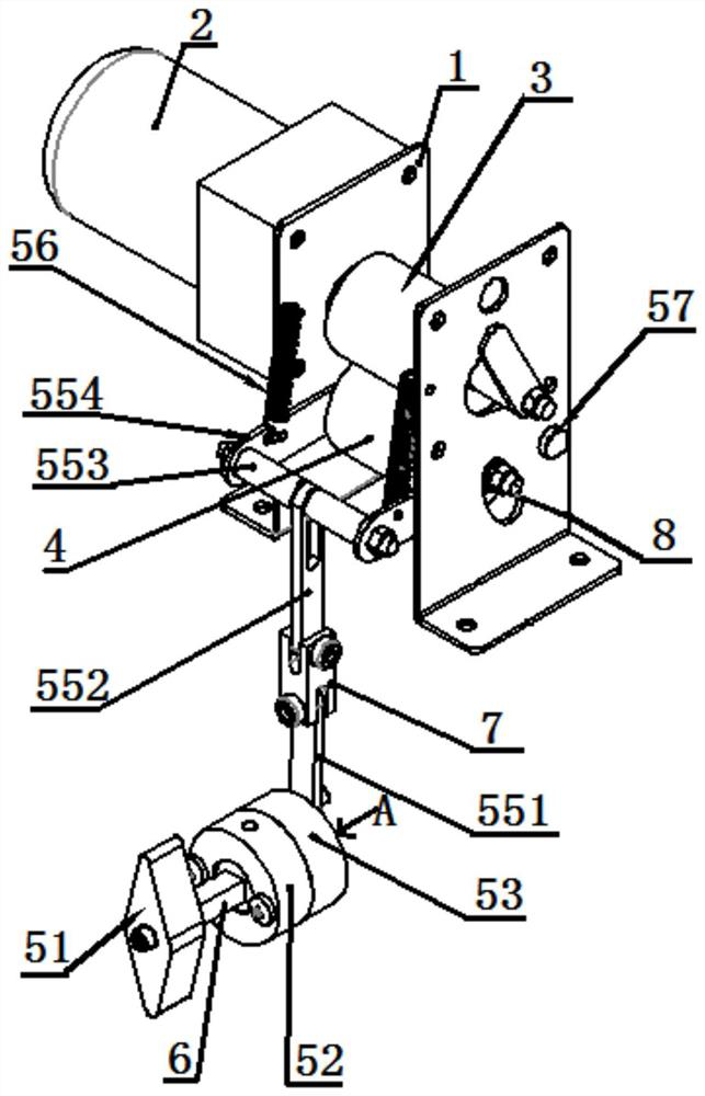
[0024] A wire feeding drive mechanism, such as figure 1 As shown, it includes installation frame 1, motor 2, wire feeding driving roller 3, wire feeding driven roller 4, gap adjustment mechanism 5, motor 2 is installed on the back of installation frame 1, and wire feeding driving roller 3 is installed on the inner side of the upper part...
PUM
Abstract
The invention provides a wire feeding drive mechanism, which includes a mounting frame, a motor, a wire feeding driving roller, a wire feeding driven roller, and a gap adjustment mechanism. A motor is arranged on the back of the mounting frame, and a wire feeding driving roller and a wire feeding driving roller are arranged on the inner side of the upper part of the mounting frame. The wire feeding driven roller, the wire feeding driving roller is connected with the motor, the wire feeding driven roller is connected with the gap adjustment mechanism, and the gap adjustment mechanism includes a handle, a fixed disk, a rotating disk, a limiting mechanism, a linkage mechanism, a spring, a pin, and a handle One side is provided with a fixed plate, one side of the fixed plate is provided with a rotating plate, the handle passes through the fixed plate and is connected with the rotating plate, a limiting mechanism is arranged between the fixed plate and the rotating plate, one side of the rotating plate is connected with the linkage mechanism, and the mounting bracket The front right side is provided with a pin shaft, and the link mechanism is connected with the wire-feeding driven roller and the pin shaft, and the upper side of the link mechanism is connected with the mounting frame by a spring. The invention has reasonable structural design and is convenient to use. The handle drives the rotating disk and the linkage mechanism to realize the adjustment of the gap between the wire-feeding driving roller and the wire-feeding driven roller.
Description
technical field [0001] The invention belongs to the technical field of outlet equipment, in particular to a wire feeding drive mechanism and an outlet machine. Background technique [0002] When all kinds of industrial reels are assembled, according to the actual needs of production, the raw material cables need to be pulled out of the reels. The manual drawing (out) of the transmission line will easily lead to loose, messy, dirty and wasteful cables. When the cable is in use, it is often not to pull the wire continuously all the time. Instead, after pulling out a part of the wire, the pulling action stops, and the part of the wire is pulled out for use. [0003] Under this kind of operation, the wire reel will rotate out of the wire under the effect of tension, and the tension on the wire reel will disappear when the operation is stopped, but the wire reel will still rotate out of the wire due to the effect of inertia, so that the wire coming out of the wire reel If they ...
Claims
Application Information
Patent Timeline
Application Date:The date an application was filed.
Publication Date:The date a patent or application was officially published.
First Publication Date:The earliest publication date of a patent with the same application number.
Issue Date:Publication date of the patent grant document.
PCT Entry Date:The Entry date of PCT National Phase.
Estimated Expiry Date:The statutory expiry date of a patent right according to the Patent Law, and it is the longest term of protection that the patent right can achieve without the termination of the patent right due to other reasons(Term extension factor has been taken into account ).
Invalid Date:Actual expiry date is based on effective date or publication date of legal transaction data of invalid patent.