
Dust removal and purification device for dust-containing waste gas

A purification device and exhaust gas technology, applied in combined devices, chemical instruments and methods, and dispersed particle separation, etc., can solve problems such as affecting gas components, huge capital investment, and unfavorable overall improvement of the global climate and environment, so as to improve separation and adsorption effect, enhancing the effect of centrifugation

Inactive Publication Date: 2021-04-13
胡家应
View PDF8 Cites 0 Cited by
  • Summary
  • Abstract
  • Description
  • Claims
  • Application Information

AI Technical Summary

Problems solved by technology

On the other hand, these dusts, fumes and harmful gases gather in the working environment in the workshop, which will also affect the normal operation of workshop equipment and instruments
If these industrial gases are directly discharged into the atmosphere, it will also affect the gas composition in the atmosphere, and the atmosphere will be enriched with harmful gases, which is extremely detrimental to the overall improvement of the global climate environment.
[0003] At present, some purification technologies for industrial waste gas are disclosed in the prior art. Most of these purification technologies have average dust removal efficiency, poor removal effect of harmful gases, and huge capital investment. For example, under a certain temperature and pressure, Use selective adsorbent and selective permeable membrane to separate volatile organic compound impurities, mainly including activated carbon adsorption, condensation method and biofilm method, etc.
There are also some purification devices that use water baths to remove dust from industrial gases and adsorb harmful gases in them, but the effect of dust removal and adsorption cannot reach the expected goals, and it also causes a lot of waste of water resources.

Method used


Image

  • Dust removal and purification device for dust-containing waste gas
  • Dust removal and purification device for dust-containing waste gas

Examples


Embodiment Construction

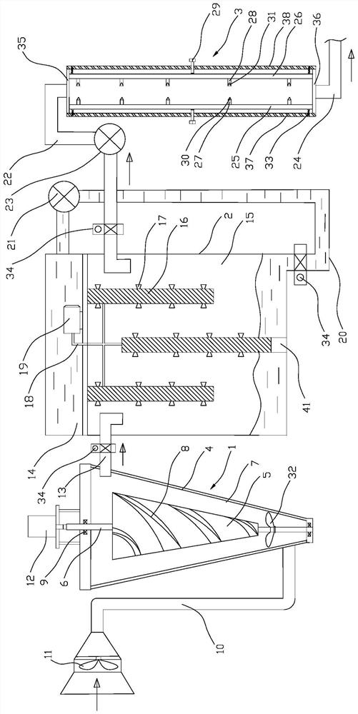
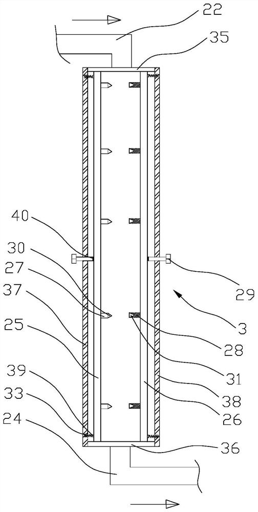
[0022] see figure 1 , a kind of dust-reducing and purifying device for dusty waste gas, comprising a cyclone dust removal box 1, an atomization box 2 and a plasma discharge chamber 3, the cyclone dust removal box 1 includes a conical outer cylinder 4, a conical wind guide hood 5, and a conical outer cylinder 4 is made up of two hinged semi-conical tubes. There is a gap between the conical outer cylinder 4 and the conical air guide 5 for the circulation of exhaust gas. The conical air guide 5 is installed on the rotating shaft 6 coaxial with it, and both ends of the rotating shaft 6 are rotated by bearings 9 Installed on the top and the bottom of the conical outer cylinder 4, fan blades 32 are installed on the bottom of the rotating shaft 6, the wind direction of the fan blades 32 is set upwards, and the upper end of the rotating shaft 6 is connected with a motor 12 in transmission, the conical outer cylinder 4 The inner wall is pasted with an oil film layer 7. When the oil fi...


PUM


Abstract

The invention discloses a dust removal and purification device for dust-containing waste gas. The device comprises a cyclone dust removal box, an atomizing box and a plasma discharge chamber, the cyclone dust removal box comprises a conical outer cylinder and a conical wind scooper, a gap allowing waste gas to circulate is formed between the conical outer cylinder and the conical wind scooper, and the conical wind scooper is installed on a rotating shaft coaxial with the conical wind scooper; and the two ends of the rotating shaft are rotationally installed at the top and the bottom of the conical outer cylinder, the upper end of the rotating shaft is in transmission connection with a motor, and an oil film layer is attached to the inner wall of the conical outer cylinder. The top of the conical outer cylinder communicates with the side wall of the atomizing box through a second ventilation pipeline. An inner cavity of the atomizing box is divided into a water storage cavity and an atomizing cavity through a horizontally-arranged partition plate. The dust removal and purification device is reasonable and compact in overall structural design, large-particle dust can be separated, fine dust and harmful gas in waste gas are subjected to dust falling and adsorption treatment through water mist, and the purification effect of industrial waste gas is further improved.

Description

technical field [0001] The invention relates to the technical field of gas dust removal and purification, in particular to a dust reduction and purification device for dusty waste gas. Background technique [0002] At present, in blast furnace smelting, thermal power generation, pharmaceutical factories and other fields, a large amount of industrial waste gas is produced every day in the production process. These industrial waste gases are various pollutant gases discharged into the air during fuel combustion and production processes. The general term of these substances, such as dust, smoke and harmful gases, etc., these substances enter the human body through the respiratory tract through different channels, some directly cause harm to the human body, and some will accumulate in the human body, which is harmful to the health of the workers in the workshop. cause great harm. On the other hand, these dusts, fumes and harmful gases gather in the working environment in the wo...

Claims


Application Information

Patent Timeline
Patent Type & Authority Applications(China)
IPC IPC(8): B01D50/00B01D53/32
CPCB01D53/32B01D50/40
Inventor 梅振胡家应
Owner 胡家应
Learn More