Portable vertical well derrick

A portable, vertical shaft technology, which is applied in the direction of sinking, drilling equipment, shaft equipment, etc., can solve the problems of inconvenient disassembly of support rods, single expansion screw fastening, large swing of traction rope, etc., and achieves convenient transportation and installation, and stable connection The effect of firmness and small swing angle

Active Publication Date: 2019-11-22
河南豫科电气有限公司
View PDF9 Cites 2 Cited by
  • Summary
  • Abstract
  • Description
  • Claims
  • Application Information

AI Technical Summary

Problems solved by technology

[0003] However, the shaft derricks in the current market will have the following problems during use. a. The existing shaft derricks are usually fastened with expansion screws when they are connected to the cement pouring layer. Because the tops of the expansion screws need to be fitted with nuts Connection, while the nut and the screw are exposed to the air for a long time, it is easy to oxidize and produce rust, which causes the problem of difficult disassembly. At the same time, the single expansion screw is used for fastening, which cannot effectively ensure the stability and firmness of the connection point; b. The main support rods of the existing shaft derricks are all formed by integrated casting, resulting in a large volume of the support rods, which is inconvenient for long-distance transportation. .When the existing shaft derrick transports the materials in the well, the vertical shaft derrick cannot maintain the stability of the traction rope rising, resulting in the excessive swing of the traction rope, and the transported materials are easy to scatter

Method used


Image

  • Portable vertical well derrick
  • Portable vertical well derrick
  • Portable vertical well derrick

Examples


Embodiment Construction

[0023] In order to make the technical problems, technical solutions and beneficial effects to be solved by the present invention clearer, the present invention will be further described in detail below in conjunction with the accompanying drawings and embodiments. It should be understood that the specific embodiments described here are only used to explain the present invention, not to limit the present invention.

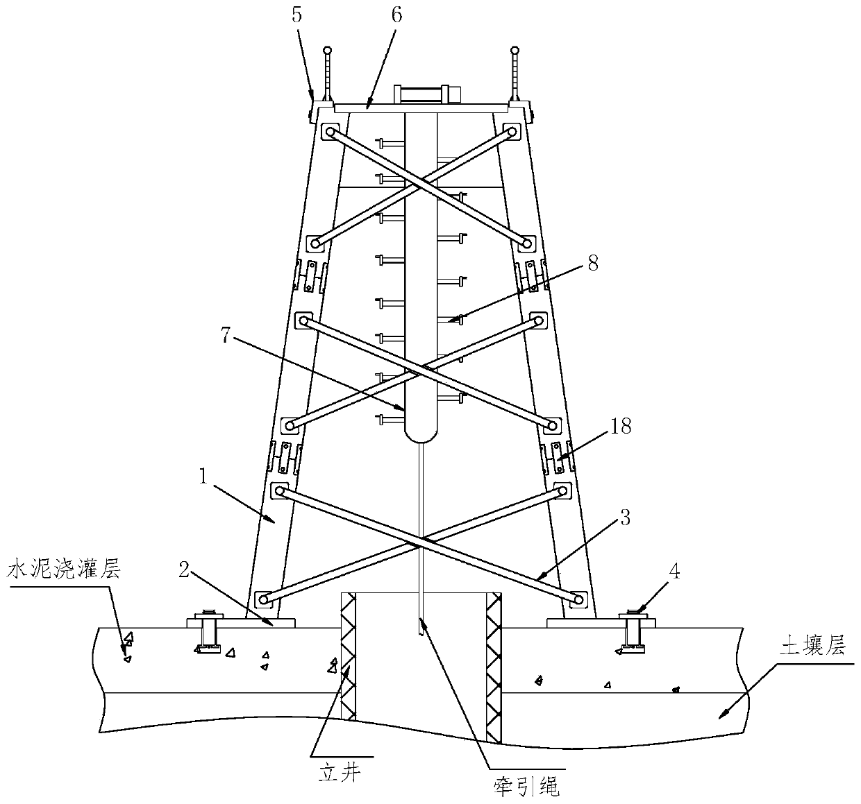
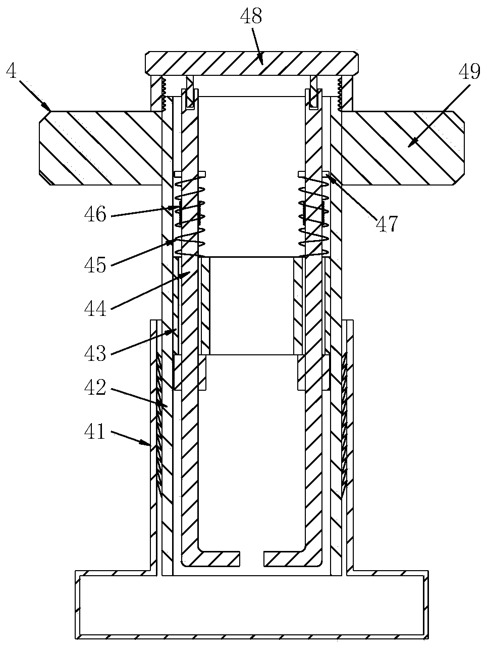
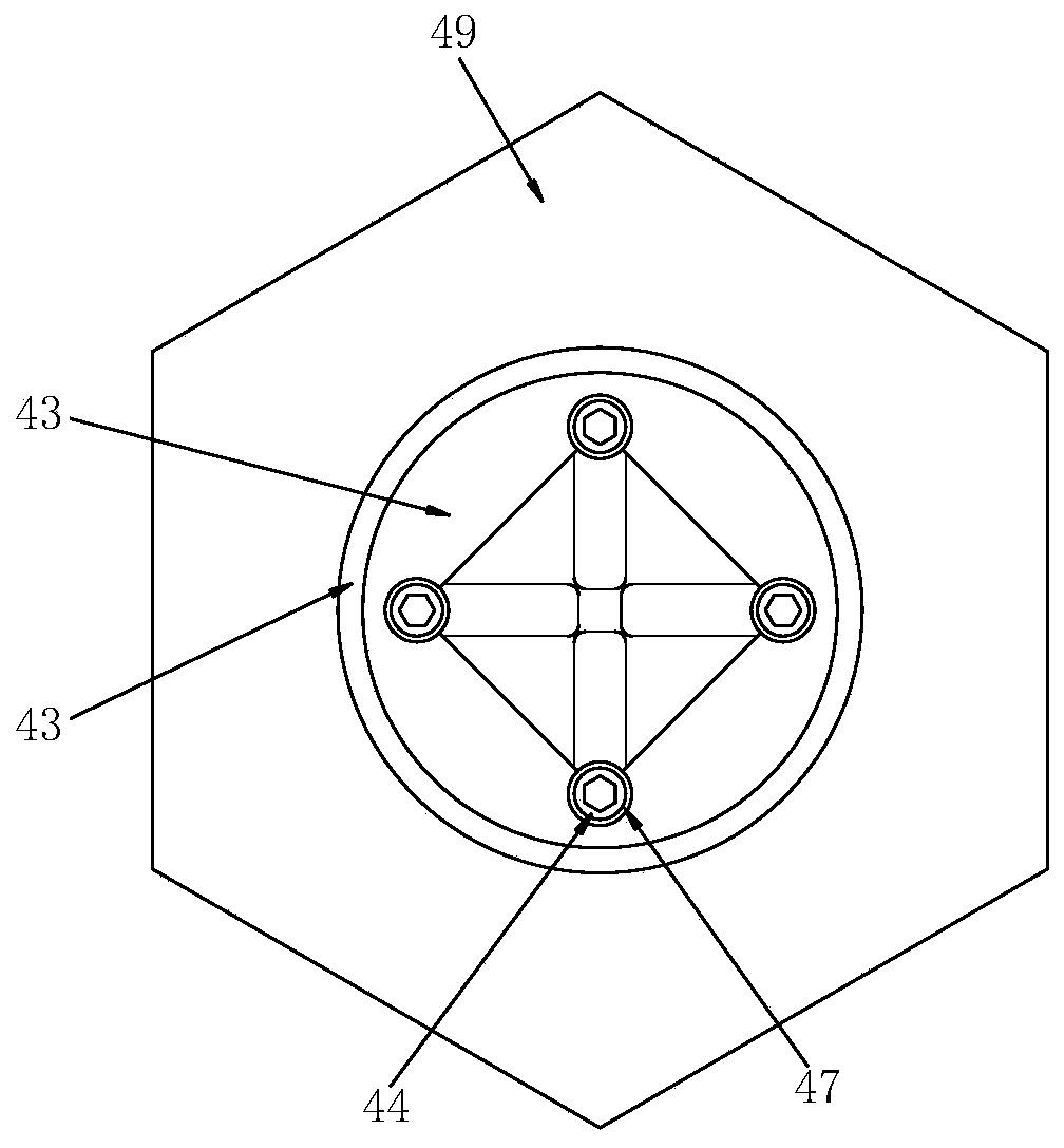
[0024] Referring to 1-5, a portable shaft derrick includes a support rod 1, a bottom plate 2, a reinforcing rod 3, a fixing mechanism 4, a safety railing 5, a working plate 6, a round rod 7 and a balance mechanism 8, and the support rod 1 The number is three, and the lower end of the support rod 1 at the bottom is welded with a bottom plate 2, the bottom plate 2 is connected with the cement pouring layer through the fixing mechanism 4, and the connection between the inside of the bottom plate 2 and the fixing mechanism 4 is provided with a connecting round hole, and...


PUM


Abstract

The invention relates to a portable vertical well derrick. The portable vertical well derrick comprises three supporting rods, bottom plates, reinforcing rods, fixing mechanisms, safety rails, a working plate, a circular rod and balance mechanisms, wherein the bottom plates are welded to the lower ends of the supporting rods at the bottoms, the bottom plates are connected with cement pouring layers through the fixing mechanisms, connecting circular holes are formed in joints of the interiors of the bottom plates and the fixing mechanisms, the reinforcing rods are fixed to the outer walls of the supporting rods through bolts, and the two reinforcing rods are installed in a cross mode. The working plate is arranged at the upper ends of the supporting rods at the tops, the working plate and the supporting rods are fastened through bolts, and the safety rails are arranged on the outer side of the working plate. The connection stability between the portable vertical well derrick and the cement pouring layers is high, the firmness is high, the long-distance transportation is convenient, assembly and disassembly are simple and convenient, the stability of materials conveyed in a well by atraction rope is effectively ensured, so that a transported material is not prone to scattering.

Description

technical field [0001] The invention relates to the technical field of shaft engineering construction, in particular to a portable shaft derrick. Background technique [0002] Shaft is a common project in underground engineering. Underground mines, mountain tunnels, water conservancy and hydropower, urban underground engineering, and military defense projects are all inseparable from the use and construction of shafts. Vertical shafts are used most in underground mines, but with the rapid development of my country's transportation and water conservancy, long-distance highways, railways, and water diversion tunnels will be excavated for construction and operation. The number of vertical shafts will also increase. The shaft derrick is a facility for serving the shaft, which can effectively help the construction personnel to transport the materials in the well to the ground. [0003] However, the shaft derricks in the current market will have the following problems during use....

Claims


Application Information

Patent Timeline
Patent Type & Authority Applications(China)
IPC IPC(8): E21B15/00E21D1/00
CPCE21B15/00E21D1/00
Inventor 赵佑黄光辉俎瑞明赵鹏郑威张世朋李军伟陈攀王新建张冬
Owner 河南豫科电气有限公司
Why Eureka
Try Eureka