Permanent magnet electromagnetic valve

A solenoid valve and permanent magnet technology, applied in the field of solenoid valves, can solve problems such as poor stability, small force, and complex structure, and achieve the effects of improving efficiency, increasing service life, and simplifying structure

Inactive Publication Date: 2019-11-22
杨妙
View PDF0 Cites 3 Cited by
  • Summary
  • Abstract
  • Description
  • Claims
  • Application Information

AI Technical Summary

Problems solved by technology

[0003] In order to fundamentally overcome the shortcomings of traditional solenoid valves such as complex structure, poor stability, small force, and short life,

Method used


Image

  • Permanent magnet electromagnetic valve
  • Permanent magnet electromagnetic valve

Examples


Embodiment Construction

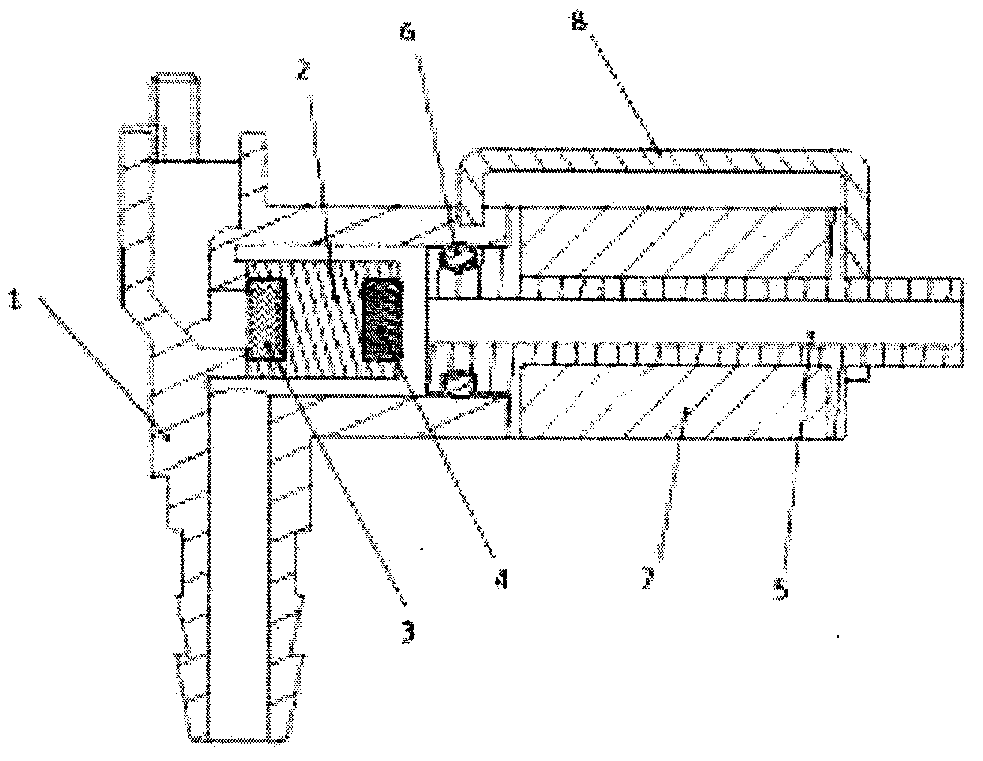
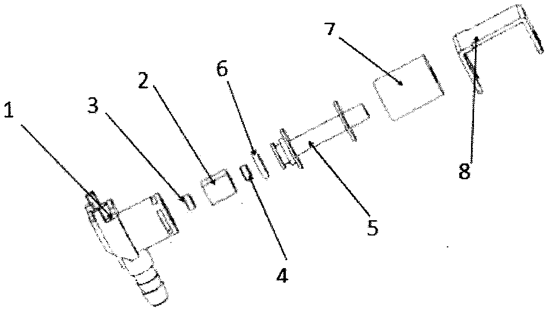
[0012] The structure of the permanent magnetic solenoid valve of the present invention is as figure 1 , figure 2 Shown, a kind of permanent magnet electromagnetic valve, it comprises valve body 1, permanent magnet spool 2 in valve body 1, left gasket 3 and right gasket 4 that permanent magnet spool 2 two ends are fixed, iron core 5 is connected on The valve body 1 and the sealing ring 6 are connected between the valve body 1 and the iron core 5, the iron core 5 is wound with a coil 7, and the iron cover 8 is connected to fix the iron core 5 and the valve body 1; when the coil 7 is energized, the iron core 5 generates Repel the electromagnetic force with the permanent magnet spool 2, push the permanent magnet spool 2 to move to the left to seal the valve port of the valve body 1 under the action of the repelling electromagnetic force, and open the valve port of the iron core 5 on the right; when the power supply of the coil 7 is disconnected, the iron The electromagnetic forc...


PUM


Abstract

The invention discloses a permanent magnet electromagnetic valve. The valve comprises a valve body and a permanent magnet valve core in the valve body, wherein a left sealing gasket and a right sealing gasket are fixed at the two ends of the valve core, an iron core is connected to the valve body, a sealing ring is connected between the valve body and the iron core, the iron core is wound with a coil, and an iron cover is connected with the iron core and the valve body and is used for fixing the iron core; when the coil is electrified, the iron core generates a magnetic pole repulsive to the permanent magnet valve core, the valve core is pushed to move leftwards under the repulsive force to seal the valve port of the valve body, and the right valve port is opened; and when the coil is notelectrified, the magnetic pole of the iron core disappears, the permanent magnet valve core moves rightwards under the action of self-magnetic force to seal the valve port of the iron core, and meanwhile, the left valve port is opened. According to the valve, a spring of a common electromagnetic valve is removed, so that the novel electromagnetic valve is simple in structure, stable and reliable.

Description

technical field [0001] The invention relates to a valve, in particular to an electromagnetic valve. Background technique [0002] Solenoid valves use energized coils to generate electromagnetic force to drive the valve core to open or close the valve and change the flow direction of the fluid. Solenoid valves are widely used in automatic control and remote control of fluids. In ordinary solenoid valves, a reaction spring is usually provided. Its structure is relatively complicated, the force is small, the stability is poor, the life is short, and it is prone to failure during use. In particular, the structure of the solenoid valve used in the control of some highly corrosive, flammable, and explosive fluids is more complicated. Contents of the invention [0003] In order to fundamentally overcome the shortcomings of traditional solenoid valves such as complex structure, poor stability, small force, and short life, [0004] The invention provides a novel electromagnetic...

Claims


Application Information

Patent Timeline
Patent Type & Authority Applications(China)
IPC IPC(8): F16K31/08
CPCF16K31/082
Inventor 杨妙
Owner 杨妙
Why Eureka
Try Eureka