Splicing method of pathological section scanning picture of microscope

A technology of pathological slices and microscopes, which is applied in the field of image processing, and can solve problems such as camera instability, small deviations, shakes, up, down, left, and right, computer inability to complete image stitching, and increased memory.

Pending Publication Date: 2019-11-22
沈熠
View PDF4 Cites 3 Cited by
  • Summary
  • Abstract
  • Description
  • Claims
  • Application Information

AI Technical Summary

Problems solved by technology

[0004] (1) Due to the high precision, during the scanning and transfer process of the microscope, the lens is prone to unstable small deviations of up, down, left and right, so there are different degrees of deviation in the scanned image;
[0005] (2) Because of the high scanning accuracy, the number of scanned pictures will inevitably increase, which will inevitably increase the memory required in the process of image stitching, which will cause ordinary computers to be unable to complete the task of image stitching

Method used


Image

  • Splicing method of pathological section scanning picture of microscope
  • Splicing method of pathological section scanning picture of microscope
  • Splicing method of pathological section scanning picture of microscope

Examples


Embodiment 1

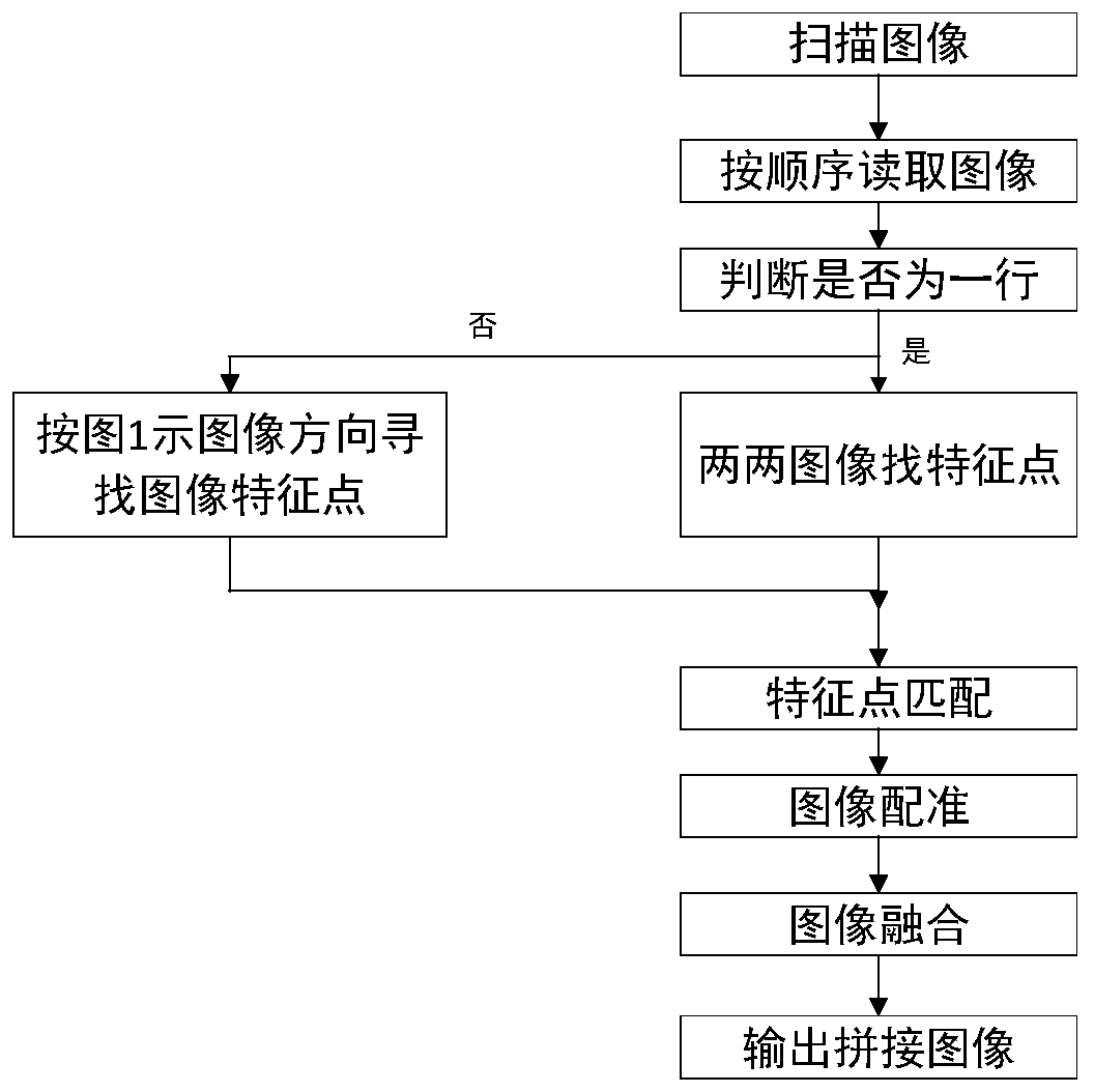
[0027] refer to figure 1 , which is the first embodiment provided in the present invention for a method for mosaicing scanned pictures of microscopic pathological sections. In this embodiment, the method for mosaicing scanned pictures of microscopic pathological sections includes the following steps:

[0028] S1, scan the image, and read the image in order, that is, read the image scanned by the high-power microscope, and place it in order.

[0029] S2, the high power microscope searches for feature points of the image.

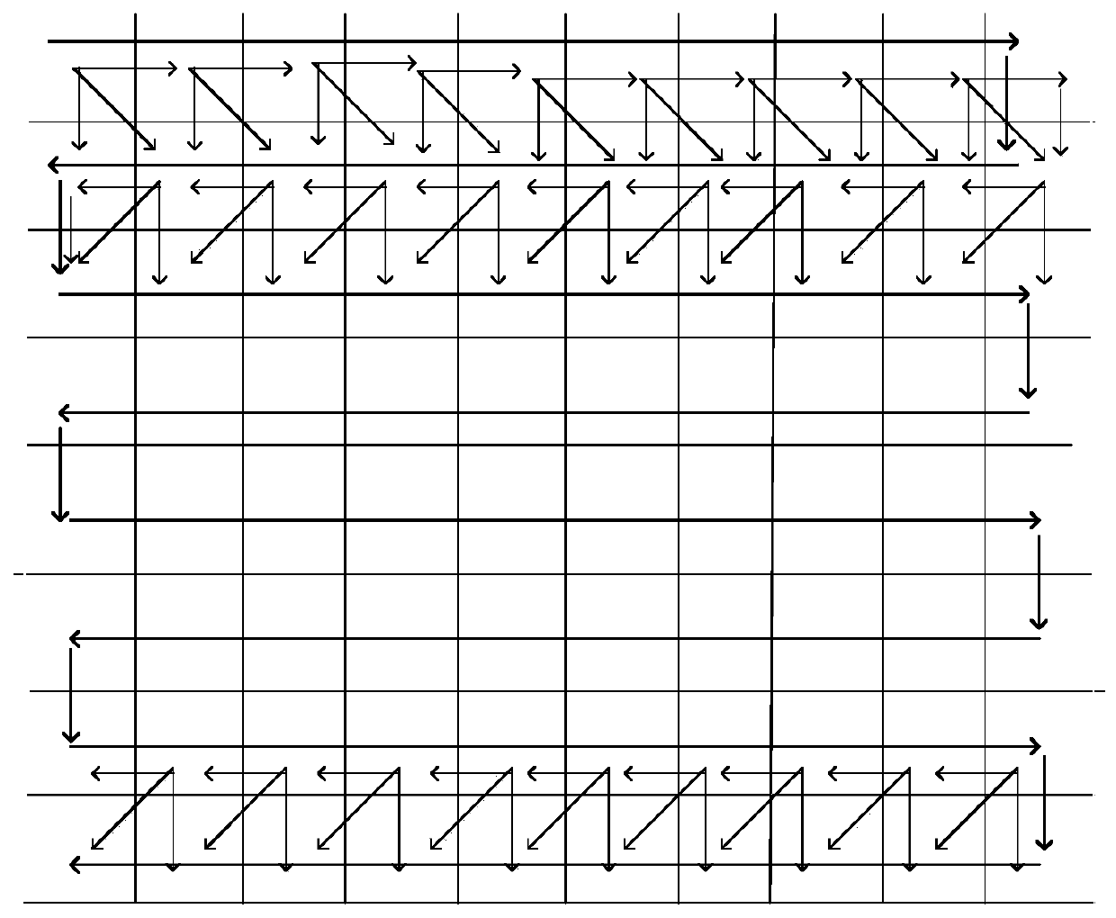
[0030] It should be noted that before looking for image feature points, it is necessary to judge whether the images are in the same line. If they are in the same line, find feature points between two images. If they are not in the same line, follow the figure 2 Find the feature points of the image in the direction indicated in .

[0031] S3, performing feature point matching on the scanned image and the image;

[0032] S4, performing image registration ac...

Embodiment 2

[0079] refer to figure 1 , which is the second embodiment provided in the method for mosaicing scanned pictures of microscopic pathological slices provided by the present invention. This embodiment is different from the first embodiment in that: in the embodiment, due to the large number of images, it is possible to It takes up a lot of memory. It is recommended to add the following two steps before starting to read the scanned image of the high-power microscope:

[0080] (1) First check your computer configuration, calculate the largest pixel m that can be spliced ​​and rendered by the computer, calculate the best number N of pictures that can be spliced ​​and rendered at one time, and then divide the images to be spliced ​​into S equal parts according to the actual situation ;

[0081] (2) Stitch and render each equal portion of the images separately according to the above steps, release the memory by deleting the spliced ​​images, and then splice each equal portion of the ...


PUM


Abstract

The invention discloses a splicing method of a pathological section scanning picture of a microscope. The method comprises the following steps: reading images scanned by a high-magnification microscope, and placing the images in sequence; the high-magnification lens microscope finding feature points of the image; carrying out feature point matching on the scanned image and the image; performing image registration according to the feature point matching result; fusing the paired image splicing boundaries by using a fusion algorithm; output of stitched images. The method is based on a high-magnification lens microscope. According to the method for splicing while scanning, feature point searching, matching, registering and fusing are conducted on an image to be spliced, a next image, an imagein the same row and the next column and diagonal images, in order to solve the memory problem, the method is combined with the actual computer configuration situation, the image to be spliced is divided into S equal parts, and then splicing is conducted.

Description

technical field [0001] The technical field of image processing involved in the present invention, in particular, relates to a method for mosaicing scanned pictures of microscope pathological sections. Background technique [0002] Image stitching technology has been applied to all aspects of social life. It is an important content in the fields of computer graphics, computer vision, and image processing. Image stitching can be obtained by shooting different locations and finally stitching to obtain high-resolution large scenes Range images, which often exceed the range of the human eye's field of vision, are also used in microscopic pathological sections. [0003] However, there are several problems in the image processing of microscope pathological slide scans on the market: [0004] (1) Due to the high precision, during the scanning and transfer process of the microscope, the lens is prone to unstable small deviations of up, down, left and right, so there are different de...

Claims


Application Information

Patent Timeline
IPC IPC(8): G06T3/40G06T7/33G06K9/46G06K9/62
CPCG06T3/4038G06T7/33G06T2207/20021G06T2207/20221G06T2207/10061G06V10/462G06V10/757
Inventor 段然梅园
Owner 沈熠
Why Eureka
Try Eureka