Surge protection device with high breaking capacity
A technology of surge protection and high breaking, which is applied in the direction of automatic disconnection emergency protection device, emergency protection circuit device, circuit device, etc., and can solve the problem of false tripping, tripping of thermal protection device, and thermal protection device without overcurrent Protective functions and other issues to achieve the effect of avoiding the risk of fire and avoiding misoperation
- Summary
- Abstract
- Description
- Claims
- Application Information
AI Technical Summary
Problems solved by technology
Method used
Image
Examples
Embodiment 1
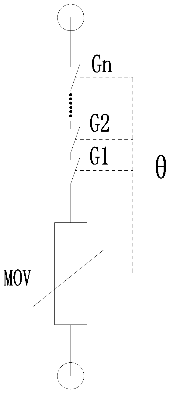
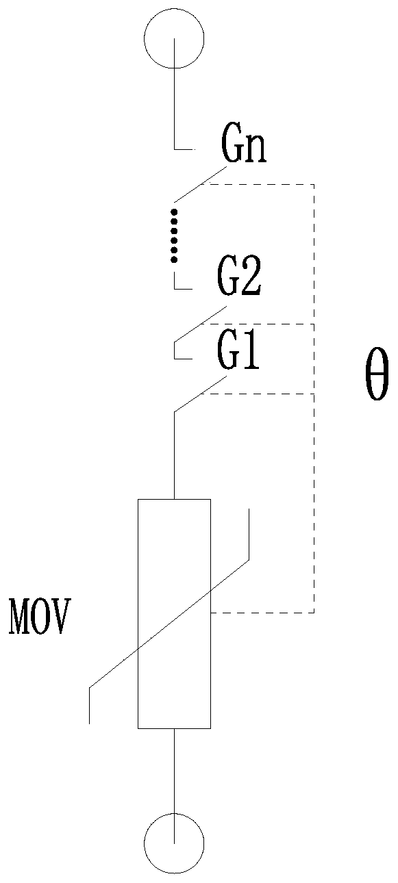
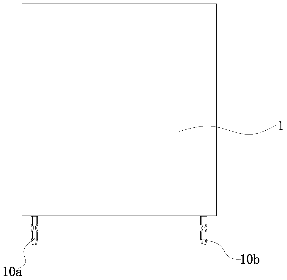
[0047] Such as Figure 1-Figure 10 As shown, this embodiment provides a surge protection device with high breaking capacity, including a housing 1 with two lead-out electrodes 10a, 10b, a voltage limiting device 2 and a thermal tripping mechanism 3 installed in the housing 1 . The circuit principle of the surge protection device is as follows figure 1 and figure 2 shown, where figure 1 Shown is the schematic diagram before operation, figure 2 Shown is a schematic diagram after operation.
[0048] Among them, refer to Figure 3-Figure 6 , the voltage-limiting device 2 includes a voltage-limiting device 20 , a first electrode 21 , a second electrode 22 and an insulating cover 23 . The voltage limiting device 20 may be a voltage limiting element such as a varistor, a transient voltage suppressor, etc. In this embodiment, the voltage limiting device 20 is taken as a varistor as an example. Both ends of the voltage limiting device 20 are electrically connected to the first e...
Embodiment 2
[0065] This embodiment also provides a surge protection device with high breaking capacity, the structure of the surge protection device is basically the same as that of the surge protection device in Embodiment 1, the difference is that reference Figure 13-Figure 15 , the application protection modes of the two are different. In the surge protection device in this embodiment, a current fuse is connected in parallel to k fractures of n (n≥2) serial fractures, where k≤n. The circuit principle of the surge protection device is as follows Figure 13-Figure 15 shown, where Figure 13 Shown is the schematic diagram before operation, Figure 14 Shown is the schematic in action, Figure 15 Shown is a schematic diagram after operation. In this embodiment, the voltage limiting device 20 is the same as that in Embodiment 1, and the voltage limiting device 20 is also taken as an example of a piezoresistor for illustration.
[0066] The surge protection device utilizes current insura...
Embodiment 3
[0069] This embodiment also provides a surge protection device with high breaking capacity. The structure of the surge protection device is basically the same as that of the surge protection device in Embodiment 1 or Embodiment 2. The surge protection device also has a remote signal switch or a window linked with the moving assembly 31 to give a failure signal.
[0070] In this embodiment, the remote signaling switch 4 is taken as an example for illustration. refer to Figure 18 and Figure 19 , the remote signaling switch 4 is fixed inside the housing 1 , and the pins of the remote signaling switch 4 extend to the outside of the housing 1 . The movable bracket 310 has a remote signal triggering part 316 that triggers the remote signaling switch 4 with the synchronous rotation of the movable bracket 310 . When the trigger metal sheet 330 is thermally tripped to cause the moving bracket 310 to rotate, the remote signaling trigger part 316 acts on the remote signaling switch 4 ...
PUM
 Abstract
Description
Claims
Application Information
 - R&D
- Intellectual Property
- Life Sciences
- Materials
- Tech Scout
- Unparalleled Data Quality
- Higher Quality Content
- 60% Fewer Hallucinations
Browse by: Latest US Patents, China's latest patents, Technical Efficacy Thesaurus, Application Domain, Technology Topic, Popular Technical Reports.
© 2025 PatSnap. All rights reserved.Legal|Privacy policy|Modern Slavery Act Transparency Statement|Sitemap|About US| Contact US: help@patsnap.com


