
Air inlet frame for rotor and generator rotor

A technology for generator rotors and air inlets, applied to magnetic circuit rotating parts, magnetic circuit shape/style/structure, etc., to achieve the effects of reducing aerodynamic noise, improving system reliability and stability, and good cooling effect

Pending Publication Date: 2019-11-22
SHEYANG ENVISION ENERGY CO LTD
View PDF0 Cites 1 Cited by
  • Summary
  • Abstract
  • Description
  • Claims
  • Application Information

AI Technical Summary

Problems solved by technology

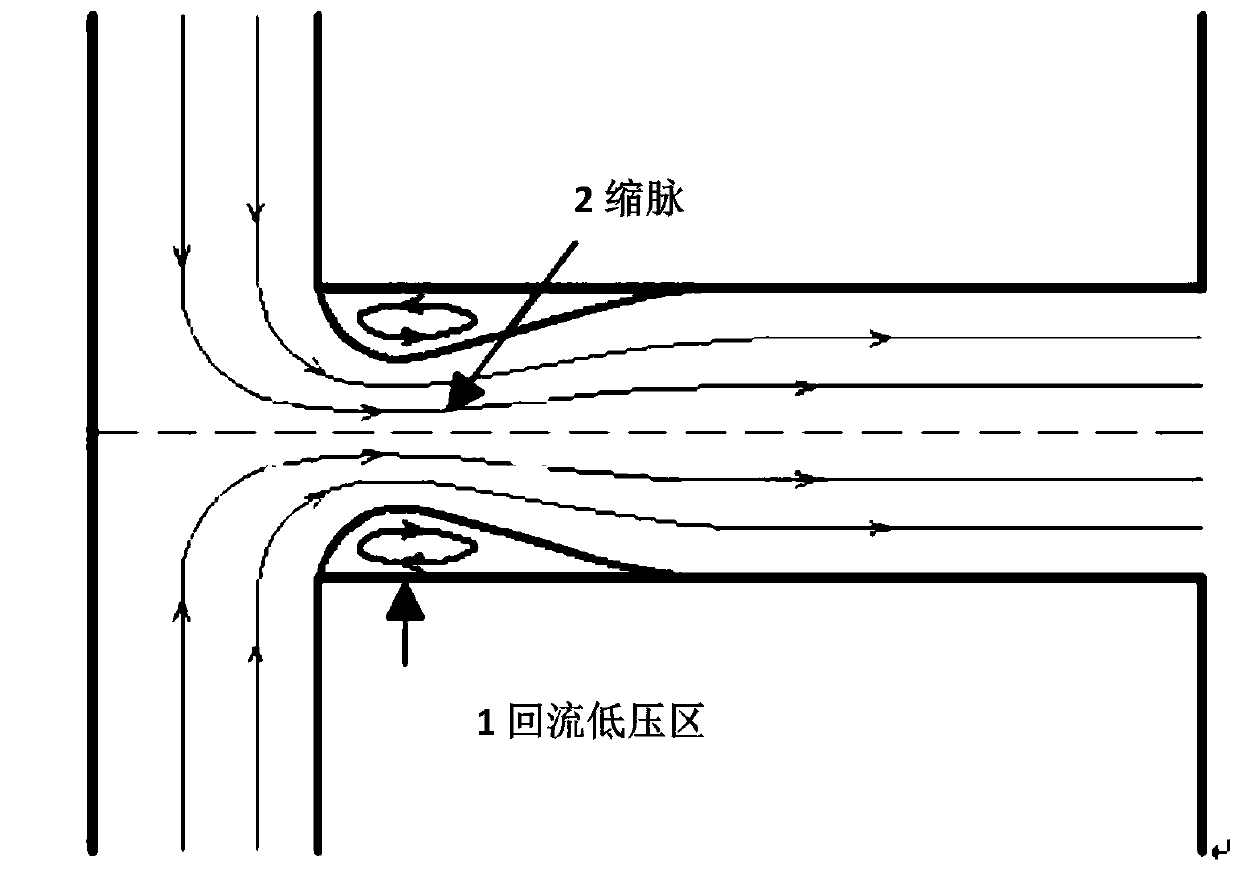
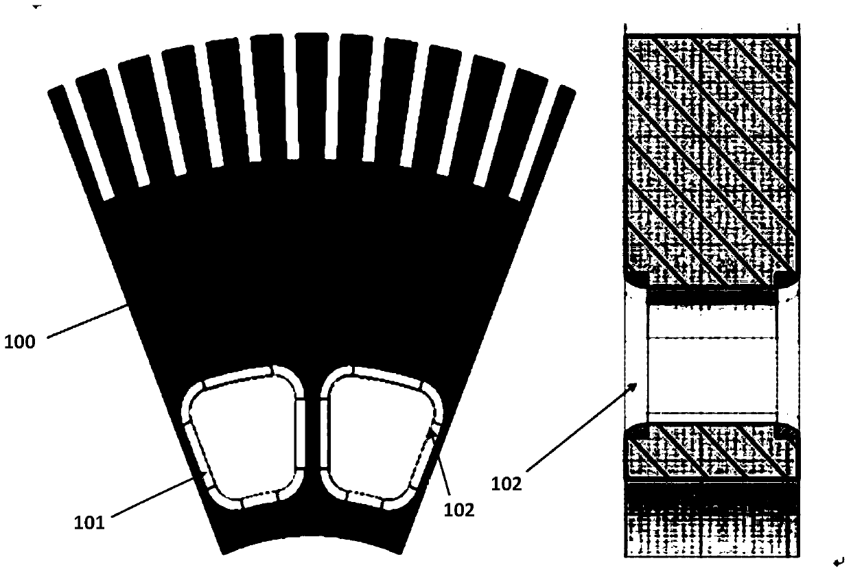
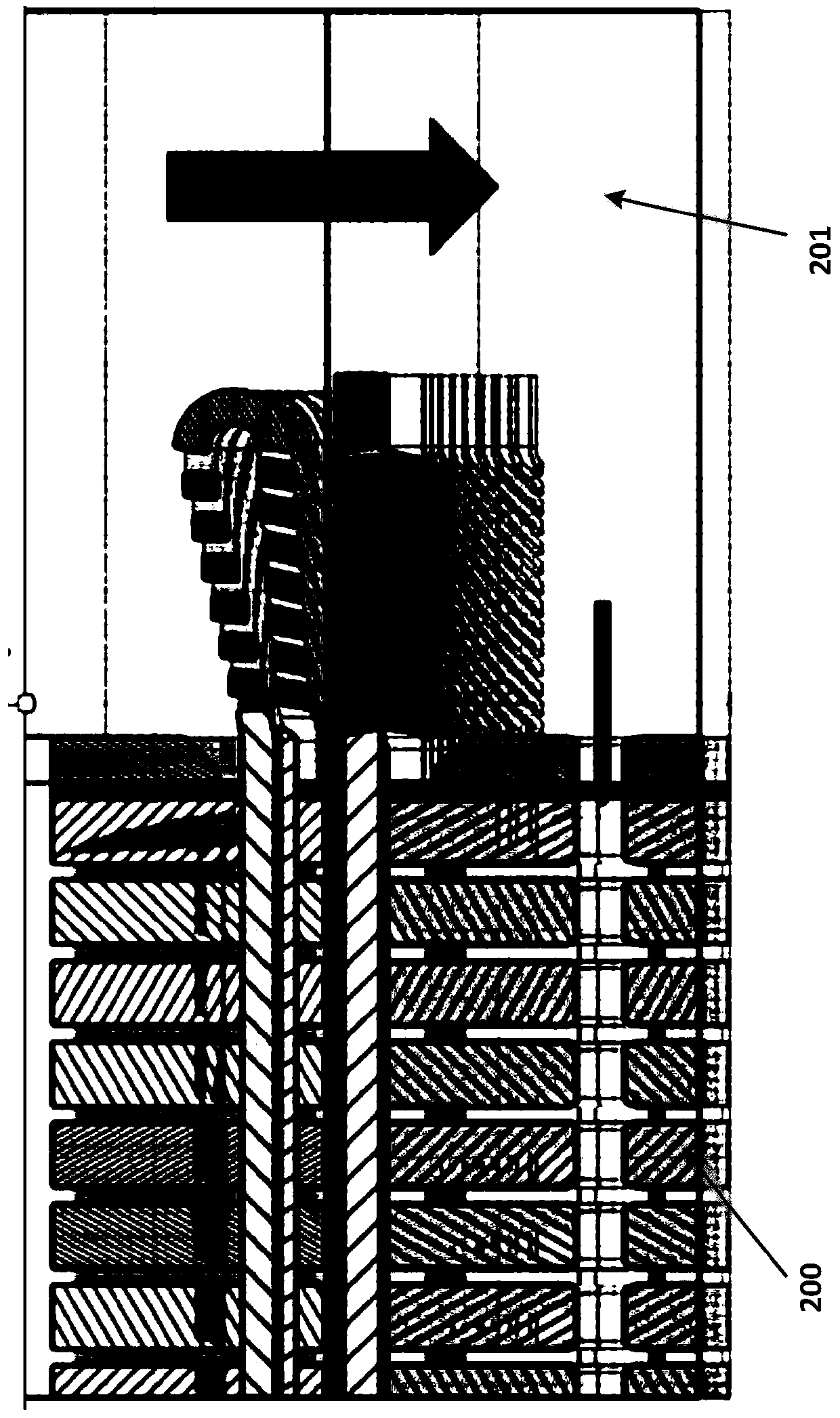
[0004] The task of the present invention is to provide an air inlet frame for a rotor and a generator rotor, by means of which air inlet frame and / or the generator rotor, the Vena Contracta phenomenon of the air inlet can be significantly reduced, by This greatly improves the air flow in the air duct inside the rotor, thereby solving the problem of aerodynamic noise and improving the heat dissipation efficiency of the rotor

Method used


Image

  • Air inlet frame for rotor and generator rotor
  • Air inlet frame for rotor and generator rotor
  • Air inlet frame for rotor and generator rotor

Examples


Embodiment Construction

[0021] It should be noted that components in the various figures may be shown exaggerated for the purpose of illustration and are not necessarily true to scale. In the various figures, identical or functionally identical components are assigned the same reference symbols.

[0022] In the present invention, unless otherwise specified, "arranged on", "arranged on" and "arranged on" do not exclude the presence of intermediates between the two. In addition, "arranged on or above" only means the relative positional relationship between two parts, and under certain circumstances, such as after the product direction is reversed, it can also be converted to "arranged under or below", and vice versa Of course.

[0023] In the present invention, each embodiment is only intended to illustrate the solutions of the present invention, and should not be construed as limiting.

[0024] In the present invention, unless otherwise specified, the quantifiers "a" and "an" do not exclude the scen...


PUM


Abstract

The invention relates to an air inlet frame for a rotor, said air inlet frame being designed to at least partially enclose an air inlet of the rotor, the inner surface of the air inlet frame having anarcuate corner. The invention also relates to a metal sheet for an engine rotor and to an engine rotor. According to the invention, the pulse shrinkage phenomenon of the air inlet can be remarkably reduced, so that the airflow flow in the internal air duct of the rotor is greatly improved, the problem of aerodynamic noise is solved, and the heat dissipation efficiency of the rotor is improved.

Description

technical field [0001] The present invention generally relates to the field of electric generators, and in particular relates to an air inlet frame for a rotor. Furthermore, the invention also relates to a generator rotor. Background technique [0002] A generator is a mechanical device that converts other forms of energy, such as wind energy and water energy, into electrical energy, and its main components are a stator and a rotor. The principle of a generator is that under the action of a source force such as wind or water, the rotor turns so that the coil cuts the magnetic field lines to generate an induced current. [0003] At present, air ducts are provided in the rotors of some generators to dissipate heat from the rotors and stators. However, the air passage structure of the existing rotor may lead to greater resistance of the internal air passage of the rotor, smaller flow generated by itself, and aerodynamic noise problems; in many cases, an additional cooling fan...

Claims


Application Information

Patent Timeline
IPC IPC(8): H02K1/22H02K1/32
CPCH02K1/22H02K1/32Y02E10/72
Inventor 俞国华雅柯·萨拉莫西尔维奥·塞默马强吴羊毫徐健华
Owner SHEYANG ENVISION ENERGY CO LTD
Learn More