

Pneumatic tire
A pneumatic tire, tire circumferential technology, applied to tire parts, tire tread/tread pattern, vehicle parts, etc., can solve problems such as partial wear and complexity, and achieve the effect of suppressing partial wear
Active Publication Date: 2019-11-26
TOYO TIRE & RUBBER CO LTD
View PDF8 Cites 2 Cited by
- Summary
- Abstract
- Description
- Claims
- Application Information
AI Technical Summary
Problems solved by technology
[0004] In the land part composed of block rows, there may be partial wear called heel-and-toe wear, and the amount of wear is different on the step-in side and the kick-out side of the block, but When the block row constituting the shoulder land portion is composed of multiple types of blocks with different shapes, the rigidity of the step-in side and the kick-out side differs for each block shape, so wear occurs: The amount of complex partial wear varies with the shape of each block
Method used
View moreImage
Smart ImageViewing Examples

Examples
Embodiment 2 and Embodiment 3
Login to View More PUM
 Abstract
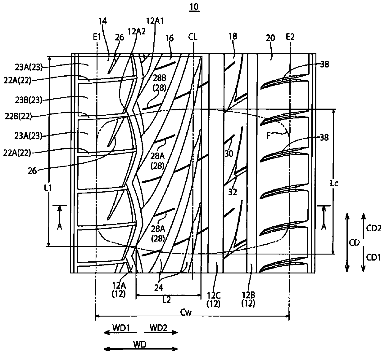
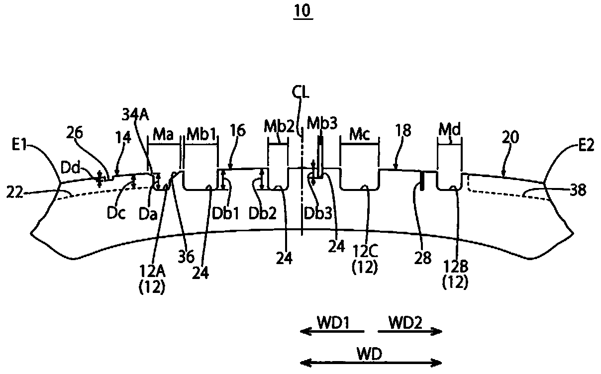
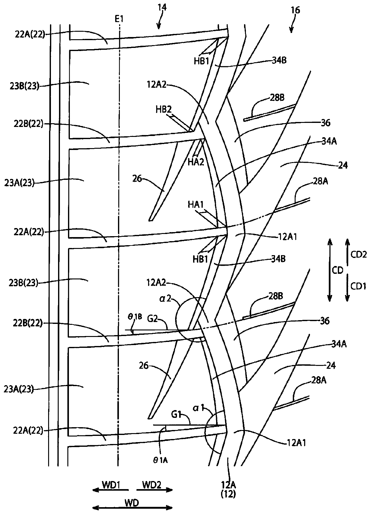
Provided is a pneumatic tire in which a shoulder land section formed between a zigzag shoulder main groove and a ground contact end is divided into a plurality of blocks in the circumferential direction of the tire by slits, and uneven wear of blocks having different shapes can be suppressed. The pneumatic tire according to the present embodiment includes a shoulder land portion (14) that is formed between a ground contact end (E1) and a shoulder main groove (12A), and a plurality of slits (22) that divide the shoulder land portion into a plurality of blocks (23) in a tire circumferential direction (CD), in which the shoulder main groove is formed of a zigzag groove in which an inward bent portion (12A1) and an outward bent portion (12A2) are alternately and repeatedly disposed, the slit is connected to the inward bent portion and the outward bent portion, in the shoulder land portion, a chamfered portion (34) is provided on a groove wall facing the shoulder main groove, and in the chamfered portion, a surface width of the chamfered portion is set to increase from the outward bent portion side toward the inward bent portion side.
Description
Technical field [0001] The present invention relates to pneumatic tires. Background technique [0002] As is well known, there are conventional pneumatic tires in which a narrow groove-shaped slit that opens in the shoulder main groove is provided in the shoulder land formed between the shoulder main groove and the ground contact end, and a plurality of patterns A block row in which blocks are arranged in the tire circumferential direction constitutes a shoulder land portion (for example, refer to Patent Document 1). [0003] In such a pneumatic tire, the shoulder main groove is composed of zigzag grooves, and when the inwardly bent portion and the outwardly bent portion are connected with slits, the following is formed: The shoulder land portion composed of a block row formed by arranging two blocks of different shapes alternately upwards, wherein the above-mentioned zigzag groove is a bent portion facing inward and a bent portion facing outward in the tire It is arranged altern...
Claims
Login to View More Application Information
Patent Timeline
 Patent Type & AuthorityApplications(China)
IPC IPC(8): B60C11/01B60C11/03B60C19/00
CPCB60C11/01B60C11/03B60C11/0304B60C11/0309B60C19/002B60C2011/013B60C2011/0353B60C2011/0355B60C2011/0376B60C2011/0379B60C2011/0365B60C11/1392B60C2011/0346B60C2011/0374B60C2011/0358B60C11/1236B60C11/13B60C2011/0372
Inventor宫崎哲二
OwnerTOYO TIRE & RUBBER CO LTD