
A Staged Energy Dissipation Damper

A staged, damper technology, applied in the direction of building types, buildings, building components, etc., can solve the problems of long repair period of buildings, residual deformation, damage of structural components, etc., to achieve firm and effective connection, good energy consumption effect, convenient The effect of replacement

Active Publication Date: 2020-09-22
YANSHAN UNIV
View PDF8 Cites 0 Cited by
  • Summary
  • Abstract
  • Description
  • Claims
  • Application Information

AI Technical Summary

Problems solved by technology

The prefabricated structure has the advantages of being green and convenient. However, the nodes of this structure have defects of low stiffness at the joints. Under the action of earthquakes, damage is easy to occur from the nodes, which reduces the reliability of the entire structure. Therefore, the seismic resistance of the prefabricated structure nodes Design has always been the focus of research
[0003] The traditional seismic design concept allows structural lateral force-resistant components to dissipate seismic energy through plastic deformation, but this will lead to damage and residual deformation of structural components. After the earthquake, the repair period of the building is long and the repair cost is considerable.

Method used


Image

  • A Staged Energy Dissipation Damper
  • A Staged Energy Dissipation Damper
  • A Staged Energy Dissipation Damper

Examples


Embodiment Construction

[0024] Below in conjunction with accompanying drawing and specific embodiment the present invention is described in further detail:

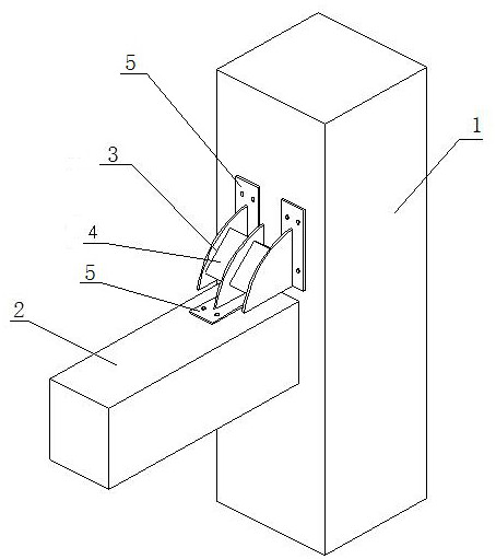
[0025] The invention discloses a staged energy-dissipating damper, specifically a staged energy-dissipating mild steel damper installed at the joint corners of frame beams and frame columns, which can quickly restore buildings after earthquakes Use function. Its structure will be described in detail below.

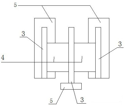
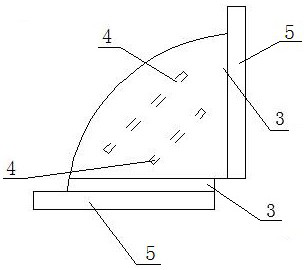
[0026] Such as figure 1 As shown, the staged energy dissipation damper includes a connecting plate 3 and an energy dissipation plate 4; the damper is installed at the angle formed by the frame column 1 and the frame beam 2. Two energy-dissipating plates 4 are arranged. By setting the two energy-dissipating plates 4 on the inside and the outside, the distances between the two energy-dissipating plates 4 and the center of rotation are different. The sizes are different to achieve staged energy consumption under earthquake damage. The conne...


PUM


Abstract

The invention relates to a damper with a staging energy consumption function, and belongs to the technical field of building structural engineering. The damper comprises two energy consumption platesand connecting plates. The two energy consumption plates are arranged in the corner between a frame beam and a frame column and conduct staging energy consumption. The connecting plates are used for connecting the energy consumption plates with the frame beam and the frame column. The distances between the two energy consumption plates and the center of rotation are different. The connecting plates and the energy consumption plates are connected through welded joints. The distance between the energy consumption plate on the inner side and the center of rotation and the distance between the energy consumption plate on the outer side and the center of rotation are different. Along with the increase of the rotational angle, the energy consumption plate on the outer side consumes energy, thenthe energy consumption plate on the inner side consumes energy, and then staging energy consumption is achieved. Compared with an existing damper, the damper with the staging energy consumption function has the advantage of achieving the better energy consumption effect. The damper with the staging energy consumption function is simple in structure, the most of connection is bolted connection, andthe assembling operation can be achieved. After an earthquake happens, seismic reduction and energy dissipation can be conducted, replacement is convenient, and the damper with the staging energy consumption function can be widely applied to the technical field of seismic reduction and energy dissipation of building structures.

Description

technical field [0001] The invention relates to a staged energy dissipation damper, which belongs to the technical field of building structure engineering. Background technique [0002] The production mode of the traditional construction industry can no longer meet the needs of the development of the times. The State Council has put forward requirements for green buildings, and the prefabricated buildings are in line with the connotation of building industrialization and greening. The prefabricated structure has the advantages of being green and convenient. However, the nodes of this structure have defects of low stiffness at the joints. Under the action of earthquakes, damage is easy to occur from the nodes, which reduces the reliability of the entire structure. Therefore, the seismic resistance of the prefabricated structure nodes Design has always been the focus of research. [0003] The traditional anti-seismic design concept allows structural lateral force-resistant co...

Claims


Application Information

Patent Timeline
Patent Type & Authority Patents(China)
IPC IPC(8): E04B1/98E04H9/02E04B1/58
CPCE04B1/58E04B1/98E04H9/021
Inventor 刘建明杨静雯闫舒茂
Owner YANSHAN UNIV
Learn More