Manufacturing method of motor rotor and motor rotor

A technology of a motor rotor and a manufacturing method, which is applied in the manufacture of stator/rotor body, magnetic circuit rotating parts, magnetic circuit shape/style/structure, etc., can solve problems such as poor production efficiency, and achieve the effect of improving low production efficiency

Active Publication Date: 2021-05-04
KAORI HEAT TREATMENT COMPANY
View PDF7 Cites 0 Cited by
  • Summary
  • Abstract
  • Description
  • Claims
  • Application Information

AI Technical Summary

Problems solved by technology

[0003] The main purpose of the present invention is to provide a method for manufacturing a motor rotor, which is used to improve the poor production efficiency of the motor rotor to be processed in a vacuum furnace in the prior art.

Method used


Image

  • Manufacturing method of motor rotor and motor rotor
  • Manufacturing method of motor rotor and motor rotor
  • Manufacturing method of motor rotor and motor rotor

Examples


Embodiment Construction

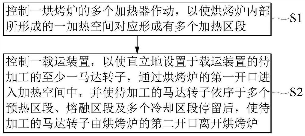
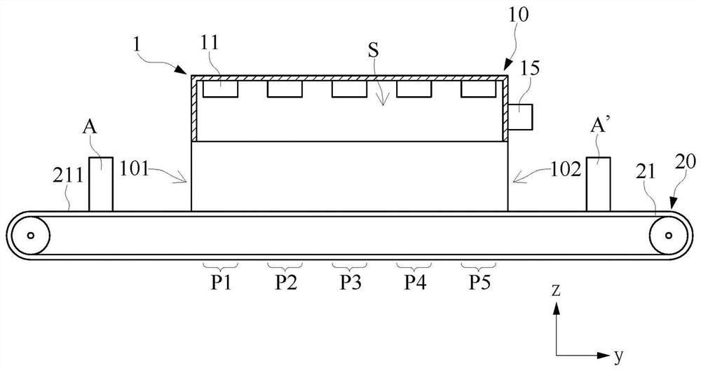
[0028]Please refer tofigure 1 andfigure 2 ,figure 1 A flow schematic of the method of manufacturing the motor rotor of the present invention,figure 2 A baking furnace according to the method of manufacturing the motor rotor of the present invention. Such asfigure 1 As shown, the method of manufacturing the motor rotor of the present invention contains the following steps:

[0029]One preparing step S1: controls the plurality of heaters of the baking furnace to operate to enable a plurality of heating segments in which a heating space formed inside the baking furnace is formed.

[0030]A heating step S2: Controls a carrier device to enable at least one motor rotor to be machined in the carrier to enter the heating space through the first opening of the baking furnace, and the motor rotor to be processed in more After the preheating section, the molten segment and the plurality of cooling zones are left, the motor rotor to be processed is separated from the second opening of the baking furn...


PUM


Abstract

A manufacturing method of a motor rotor includes a preparation step and a heating step. The preparation step is: controlling the operation of a plurality of heaters of a baking oven, so that a heating space formed inside the baking oven is correspondingly formed with a plurality of heating sections. The heating step is: controlling a carrier device so that at least one motor rotor to be processed, which is vertically arranged on the carrier device, enters the heating space through the first opening, and the motor rotor to be processed is sequentially placed in a plurality of preheating sections , after the melting section and the plurality of cooling sections stay, the motor rotor to be processed leaves the baking oven through the second opening. The manufacturing method of the motor rotor of the present invention does not need to perform the evacuation operation before heating the motor rotor. Therefore, the known vacuum furnace heating the motor rotor requires a lot of time to perform the evacuation operation, resulting in low production efficiency. question.

Description

Technical field[0001]The present invention relates to a method of manufacturing a motor rotor, in particular a method for producing a motor rotor primarily made of a copper material and a motor rotor primarily made of copper material.Background technique[0002]In a manner, there is a lot of problems in actual implementation using a vacuum oven to the motor rotor to make the associated solder of the motor rotor to each other. For example, the vacuum furnace must first take a vacuum job before heating, and then heating operation can then be heated, and therefore, when carrying a large number of production operations, the motor rotor is used to heat the motor rotor, and it takes a lot of time. . In addition, if the relevant industry wants to increase the number of motor rotors in the vacuum furnace, it is necessary to increase the vacuum furnace, which in turn leads to an increase in the purchase cost of the vacuum furnace. In view of this, how to quickly and plenty of work quickly and ...

Claims


Application Information

Patent Timeline
Patent Type & Authority Patents(China)
IPC IPC(8): H02K15/02H02K1/22H02K1/32
CPCH02K1/22H02K1/32H02K15/02
Inventor 陈建和李青峻李俊颖王琬琦
Owner KAORI HEAT TREATMENT COMPANY
Why Eureka
Try Eureka