A right-angle guide rail and cabinet

A technology for right-angle guide rails and cabinets, applied in the field of guide rails, can solve the problems of difficulty in guaranteeing the machining accuracy of sheet metal cabinets, limited adjustment clearance of L-shaped right-angle guide rails, and difficulty in adjusting the installation form, and achieves improved adjustment efficiency, strong applicability, and reduced adjustment. The effect of speed and precision

Active Publication Date: 2020-12-18
BEIJING MECHANICAL EQUIP INST
View PDF5 Cites 0 Cited by
  • Summary
  • Abstract
  • Description
  • Claims
  • Application Information

AI Technical Summary

Problems solved by technology

[0002] At present, a large number of plug-in cabinets are used in power supply products, especially 19-inch standard cabinets. The plug-in cabinets are generally inserted and pulled out along the L-shaped right-angle guide rails installed on the cabinet. With the continuous improvement of use requirements, According to the relevant standards, the gap between the upper and lower adjacent two sub-box panels is generally 0.8 mm, and the requirements for the installation accuracy of the sub-boxes in the cabinet are getting higher and higher, especially the requirements for the adjustment of the installation position in the vertical direction are very high, and the panel The processing accuracy of the metal cabinet is difficult to guarantee, so a lot of energy is often spent on adjusting the position of the L-shaped right-angle guide rail of the subrack when assembling the cabinet. On the other hand, the adjustment clearance of the traditional L-shaped right-angle guide rail is very limited. At present, the traditional L-shaped right-angle guide rail The adjustment is generally to adjust the up and down height of the guide rail through the long round hole on the guide rail. This installation form is difficult to adjust. When the up and down position of the guide rail needs to be adjusted, the sub-box on the guide rail needs to be removed, so as to have room for operation by loosening the fixed guide rail. Screws to adjust the height of the guide rail, then tighten the screws, and then check whether the position of the subrack in the cabinet is appropriate after loading it into the subrack. This adjustment method is extremely inefficient; The friction force of the installation bolts is used to keep the relative position of the guide rails from moving, and the reliability is low. Although the position is temporarily adjusted, the box will sink and shift due to insufficient friction provided by the installation bolts during the vibration process.

Method used


Image

  • A right-angle guide rail and cabinet
  • A right-angle guide rail and cabinet
  • A right-angle guide rail and cabinet

Examples


Embodiment 1

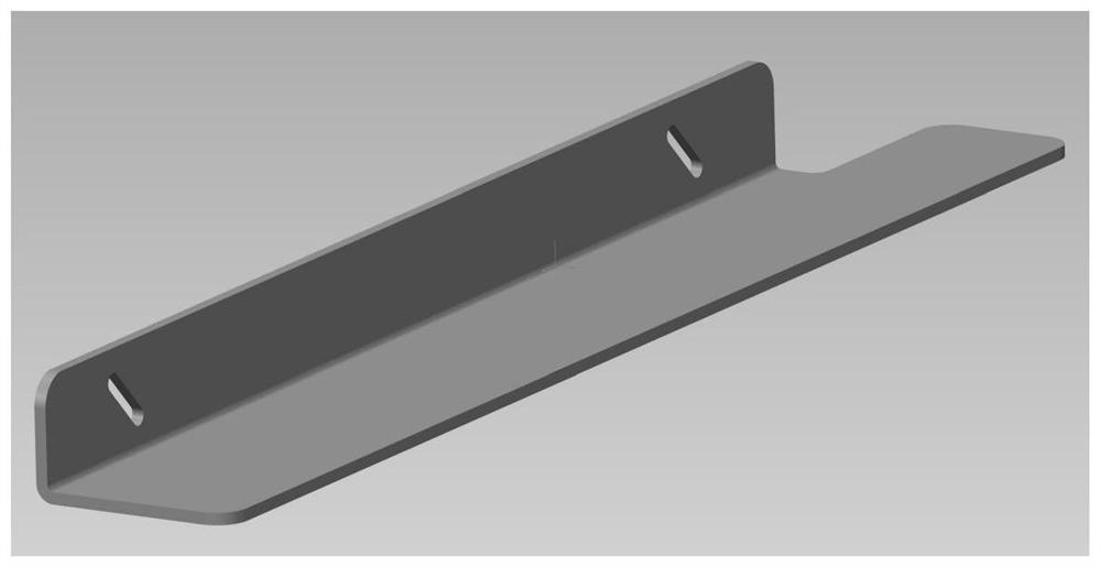
[0033] This embodiment discloses a right-angle guide rail, such as Figure 2-4 As shown, the right-angle guide rail includes a male rail 1 and a female rail 2; the female rail 2 includes a base 21 and a slide rail 22, the base 21 is a cuboid, and the slide rail 22 is arranged on the side of the base 21, along the length direction of the base 21 Extension; the upper surface of the base 21 is provided with a connecting portion 23, and the connecting portion 23 is a parallelepiped whose longitudinal section is a parallelogram; the male track 1 is a cuboid, and the male track 1 is provided with a groove 4 cooperating with the connecting portion 23; Track 1 and parent track 2 are movably connected.

[0034] Compared with the prior art, the female track provided in this embodiment is provided with a connecting part 23 whose longitudinal section is a parallelogram, and a groove matching the connecting part 23 is provided on the male track, and the male track 1 and the female track 2 ...

Embodiment 2

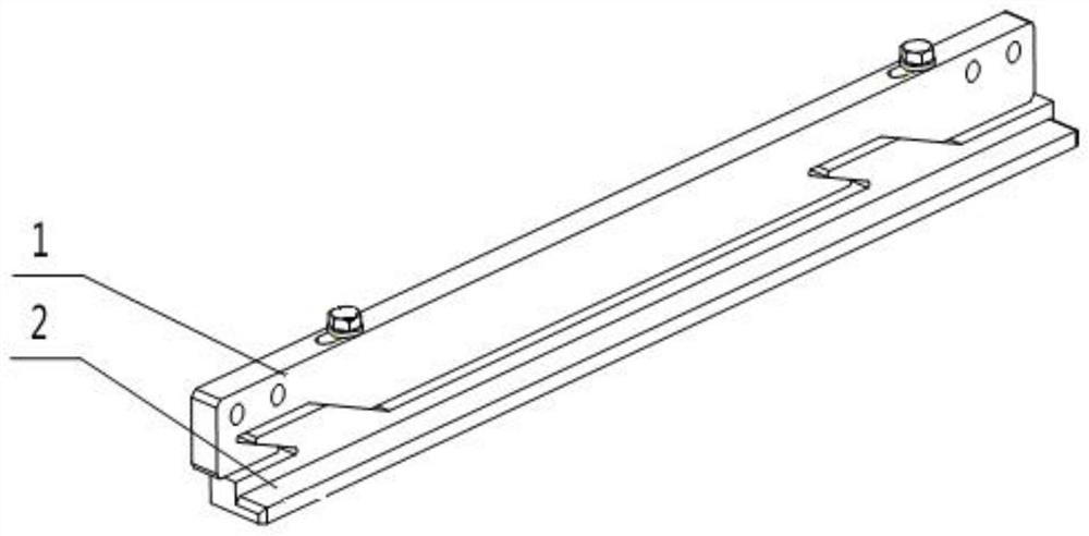
[0053] This embodiment discloses a right-angle guide rail, such as Figure 2-4 As shown, the right-angle guide rail includes a male rail 1 and a female rail 2; the female rail 2 includes a base 21 and a slide rail 22, the base 21 is a cuboid, and the slide rail 22 is arranged on the side of the base 21, along the length direction of the base 21 Extension; the upper surface of the base 21 is provided with a connecting portion 23, and the connecting portion 23 is a parallelepiped whose longitudinal section is a parallelogram; the male track 1 is a cuboid, and the male track 1 is provided with a groove 4 cooperating with the connecting portion 23; The track 1 and the parent track 2 are movably connected, specifically, the base 21 of the parent track 2 has a length of 400 mm.

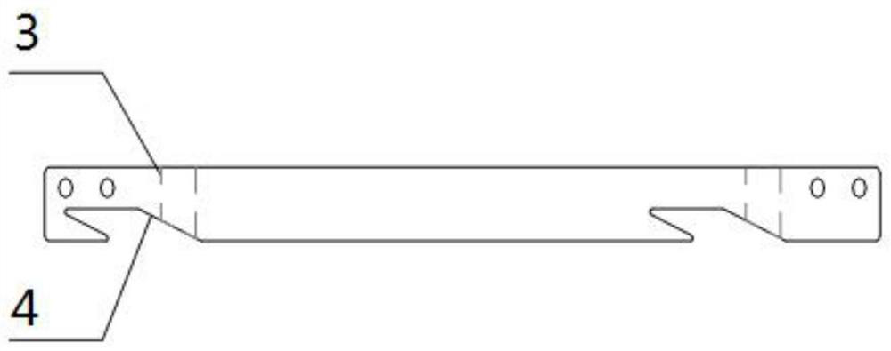
[0054] Specifically, a waist-shaped through hole 3 is provided on the upper surface of the male rail 1, and a threaded hole is provided on the connecting portion 23, and the bolt passes through the waist-sh...

Embodiment 3

[0063] This embodiment discloses a cabinet, such as Figure 5 As shown, including the cabinet main body 6 and the right-angle guide rail 5 provided in Embodiment 1, the cabinet main body is provided with columns for installing the right-angle guide rails, and the right-angle guide rails are installed and fixed on the columns on both sides of the cabinet main body through the mounting holes on the male rail. Install and use in pairs.

[0064] During the implementation, the subrack is placed on the right-angle guide rail. Compared with the traditional technology, when adjusting the position of the subrack, it is not necessary to remove the subrack above the guide rail first, and it is not necessary to roughly adjust the height of the guide rail by loosening the bolts of the guide rail and the cabinet. , rely on the experience of the operator to evaluate whether the height of the guide rail is appropriate, and then reinsert the subrack into the cabinet to confirm whether the heig...


PUM


Abstract

The invention relates to a right-angle guide rail and a cabinet, belongs to the technical field of guide rails, and solves the problem that an existing right-angle guide rail has poor height adjustment precision, low adjustment efficiency and low reliability and is easy to deviate. The right-angle guide rail comprises a male rail and a female rail. The female rail comprises a base and a slide rail. The base is a cuboid. The slide rail is arranged to the side of the base, and extends in the lengthwise direction of the base. A connecting part is arranged on the upper surface of the base, and theconnecting part is a parallelepiped with a parallelogram-shaped longitudinal section. The male rail is a cuboid, and is provided with a groove matched with the connecting part. The male rail is movably connected with the female rail. The cabinet comprises a cabinet body and a right-angle guide rail. The right-angle guide rail can be accurately adjusted.

Description

technical field [0001] The invention relates to the technical field of guide rails, in particular to a right-angle guide rail and a cabinet. Background technique [0002] At present, a large number of plug-in cabinets are used in power supply products, especially 19-inch standard cabinets. The plug-in cabinets are generally inserted and pulled out along the L-shaped right-angle guide rails installed on the cabinet. With the continuous improvement of use requirements, According to the relevant standards, the gap between the upper and lower adjacent two sub-box panels is generally 0.8mm, and the requirements for the installation accuracy of the sub-boxes in the cabinet are getting higher and higher, especially the requirements for the adjustment of the installation position in the vertical direction are very high. The processing accuracy of the metal cabinet is difficult to guarantee, so a lot of energy is often spent on adjusting the position of the L-shaped right-angle guide...

Claims


Application Information

Patent Timeline
Patent Type & Authority Patents(China)
IPC IPC(8): H05K7/18
CPCH05K7/18
Inventor 孙海军
Owner BEIJING MECHANICAL EQUIP INST
Why Eureka
Try Eureka