
A winding forming roller removal device for mechanical processing platform

A mechanical processing platform and winding forming technology, applied in metal processing, metal processing equipment, manufacturing tools, etc., can solve the problems of unfavorable winding forming rollers for pipe processing, affecting the service life of winding forming rollers, and affecting the flatness of the ground, etc., to achieve Avoid oil stains sticking to the ground, easy and quick cleaning, and avoid wear and tear

Active Publication Date: 2020-11-13
东港智科产业园有限公司
View PDF6 Cites 0 Cited by
  • Summary
  • Abstract
  • Description
  • Claims
  • Application Information

AI Technical Summary

Problems solved by technology

[0003] However, the winding forming rollers currently used in the manufacture of PE winding pipes need to be replaced with new bearings after long-term rotation and the bearings inside the outer sleeve are worn or damaged. The inner bearings located in the outer sleeve are installed and fastened. The inner shaft is fixed on the ground and then the outer sleeve is tapped to separate the inner shaft, the outer shaft and the bearing to achieve the purpose of replacing the bearing. During the tapping process, the inner shaft wears the ground, which affects the flatness of the ground, and is wound on the ground. When the forming pipe is disassembled, there is a lot of dust and gravel on the ground. If the sand and gravel are bonded to the surface of the inner shaft and enter the inside of the outer shaft during the disassembly and installation process, the winding forming roller will be greatly worn during the rotation of the outer shaft. It affects the service life of the winding forming roller, which is not conducive to the processing of the pipe by the winding forming roller. At the same time, it is easy to make oil stains stick to the ground, which is not easy to clean

Method used


Image

  • A winding forming roller removal device for mechanical processing platform
  • A winding forming roller removal device for mechanical processing platform
  • A winding forming roller removal device for mechanical processing platform

Examples


Embodiment Construction

[0023] In order to make the technical means, creative features, goals and effects achieved by the present invention easy to understand, the present invention will be further described below in conjunction with specific embodiments.

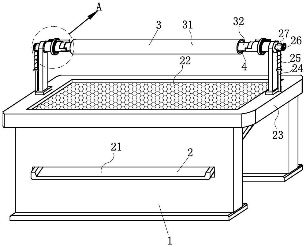
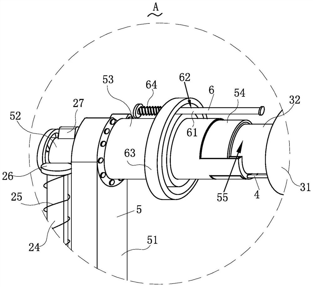
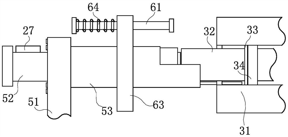
[0024] Such as Figure 1-Figure 6 As shown, a winding forming roll removal device for a mechanical processing platform according to the present invention includes a support plate 1, a cleaning mechanism 2, a forming mechanism 3, a lubricating mechanism 4, a fixing mechanism 5 and a dismounting mechanism 6; The top of the support plate 1 supported by the mechanism is relatively installed with a cleaning mechanism 2 for collecting and cleaning the dust and sand falling during the disassembly process. The fixing mechanism 5 for fixing, the forming mechanism 3 for rolling forming the pipeline is fixedly connected between the two fixing mechanisms 5, and the opposite ends of the two fixing mechanisms 5 are installed for forming the forming mechanism 3...


PUM


Abstract

The invention relates to the field of machining, in particular to a winding forming roller dismounting device for a machining platform, which comprises a support plate, a cleaning mechanism, a formingmechanism, a lubricating mechanism, a fixing mechanism and a dismounting mechanism, after the forming mechanism is mounted on the fixing mechanism, the forming mechanism is dismounted by the dismounting mechanism; when the forming mechanism is damaged and the inner shaft, the outer shaft and the bearing need to be separated and replaced, the two ends of the inner shaft penetrate through the containing grooves and extend into the fixing barrel. The fixed cylinder with the L-shaped cross section facilitates the installation of the inner shaft; the crowbar is knocked towards one end to realize contraction of the third pressure spring; the turntable positioned on the surface of the crowbar can annularly slide in the second chute; loosening of the inner shaft, the outer shaft and the bearing is achieved, the defect that an outer pipe is knocked to damage the ground when the inner shaft is placed on the ground traditionally is overcome, and on the other hand, dust and gravel are prevented from entering the space between the inner shaft and the outer shaft during ground operation to cause abrasion to the bearing and influence production when a forming mechanism is used.

Description

technical field [0001] The invention relates to the field of mechanical processing, in particular to a winding and forming roller dismounting device for a mechanical processing platform. Background technique [0002] The mechanical processing platform is the workplace that provides mechanical maintenance installation, disassembly, repair and measurement. Specifically, it provides a placement plate for the installation and disassembly of mechanical parts. The winding molding process is to make continuous fibers (or cloth tapes, pre- Dipped yarn) is wound on the mandrel according to certain rules, and then solidified and demolded to obtain products. The prepared finished products include simple tubes and complex ones that can be used to manufacture aircraft shells, automobile frames, etc. Common products include: tubes , pressure vessels, missile launch tubes, engine cases, automotive springs, fuel tank bearings, etc. [0003] However, the winding forming rollers currently us...

Claims


Application Information

Patent Timeline
Patent Type & Authority Patents(China)
IPC IPC(8): B23P19/00B08B7/02B29C70/32
CPCB08B7/02B23P19/00B29C70/32
Inventor 不公告发明人
Owner 东港智科产业园有限公司
Learn More