
Bonding mechanism and bonding method of inner bag and outer bag of double-layer bag

A double-layer bag, outer bag technology, applied in bag making operations, container manufacturing machinery, paper/cardboard containers, etc., can solve the problems of increased time required, pollution of inner bag body, wear of adhesive joints, etc., and achieve the effect of adjustment Better, prolong service life, reduce the effect of defective rate

Active Publication Date: 2021-04-20
陈坚承
View PDF9 Cites 0 Cited by
  • Summary
  • Abstract
  • Description
  • Claims
  • Application Information

AI Technical Summary

Problems solved by technology

[0004] However, in the prior art, the opening end of the inner bag body and the outer bag body is combined, and the part of the inner bag body that protrudes from the opening of the outer bag body is pushed toward the inner direction of the outer bag body until the inner bag body is closed by manual operation. The opening edge is aligned with the opening edge of the outer bag body, and then the openings are combined with each other by using the bonding machine; but because the operator directly touches the inner bag body during the operation, it may cause contamination of the inner bag body and violate relevant health regulations In addition, the combination of the opening of the inner bag body and the opening of the outer bag body is also achieved through manual adjustment, which increases the time required for the overall operation process and is not conducive to the mass production of double-layer packaging bags. In addition, the error caused by manual alignment of the opening of the inner bag and the outer bag is also more obvious
[0005] As a large number of repeated actions of automated machinery, the wear and tear of the vulnerable parts such as the bonded joint is very serious due to the long-term use of the bonded joint due to the rigid contact with the bonding surface. How to improve the service life of the bonded joint is very important for the increase in the service time of the device. And, now Some internal and external bag bonding devices have no means of controlling the bags to be bonded during the bonding process, which can easily lead to poor bonding effects due to uncontrolled bags, and even an increase in the rate of defective products

Method used


Image

  • Bonding mechanism and bonding method of inner bag and outer bag of double-layer bag
  • Bonding mechanism and bonding method of inner bag and outer bag of double-layer bag
  • Bonding mechanism and bonding method of inner bag and outer bag of double-layer bag

Examples


Embodiment 1

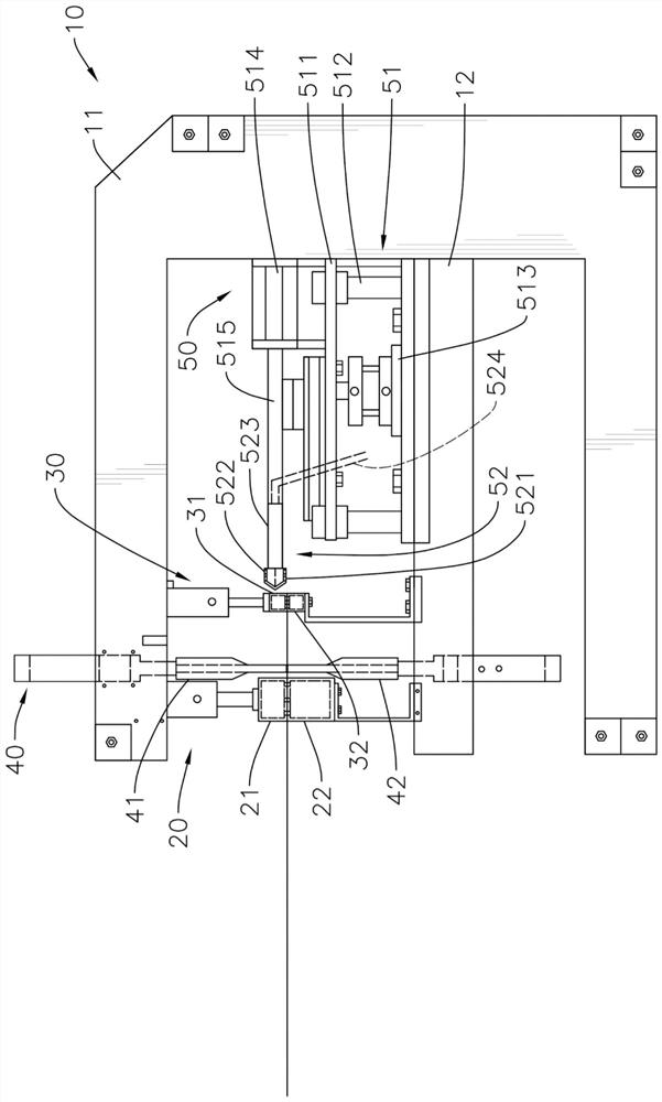
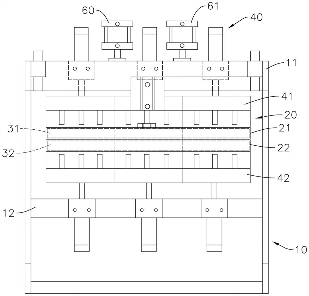
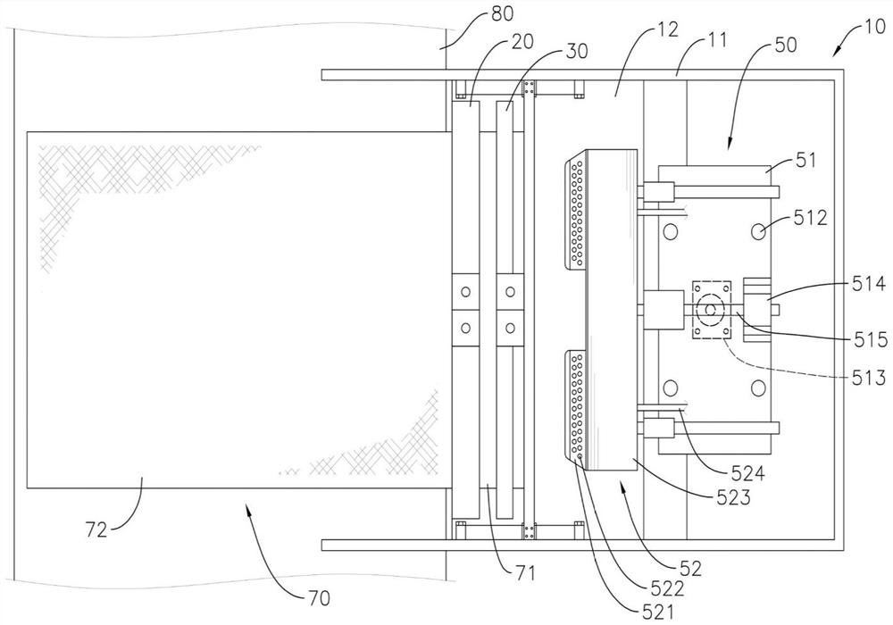
[0056] Please refer to figure 1 As shown, the bonding mechanism of the inner bag and the outer bag of the double-layer bag of the present invention includes a base 10 , a first suction cup 20 , a second suction cup 30 , an engaging device 40 and a positioning device 50 .

[0057] Please refer to image 3 and Figure 9 As shown, the double-layer bag 70 referred to in the present invention has an inner bag 71 and an outer bag 72, and one end of the inner bag 71 and the outer bag 72 has an opening respectively, and the other ends are all closed, and the inner bag 71 is located in the outer bag. 72, and one end of the opening of the inner bag 71 protrudes from the opening of the outer bag 72 to form a protrusion 711. In this embodiment, the outer bag 72 is a woven bag, and the inner bag 71 is a bag body of PE (Polyethylene) film .

[0058] Please refer to figure 1 As shown, the base 10 has an upper seat 11 and a lower seat 12; in the present embodiment, the base 10 is a simila...

Embodiment 2

[0082] see Figure 11 and 12 As shown, the difference between this embodiment and Embodiment 1 is that a flattening device 43 is movable on the upper joint 41, and the flattening device 43 includes a pressing bag 431 and a reset device 432, and the pressing bag 431 is arranged on the side of the upper joint 41 outer periphery, and is flexibly connected with the upper joint 41 through the reset device 432, the bottom of the pressure bag 431 is a structure formed by points and / or lines and / or surfaces, the bottom structure of the pressure bag 431 is horizontal and coplanar, and the reset device 432 is elastic Reset device, and the elastic expansion and contraction direction is consistent with the moving direction of the upper joint 41, the pressure bag 431 can move in the expansion and contraction direction of the reset device 432, the adhesive end of the upper joint 41 is located within the movement range of the bottom end of the pressure bag 431, the upper joint When 41 moves...

Embodiment 3

[0094] Such as Figure 14As shown, the structure of the device is further optimized. Compared with Embodiment 2 in this embodiment, the third suction cup 52 further includes a pressing plate 523 and a bag supporting device 525. The pressing plate 523 is arranged horizontally. The number of bag supporting devices 525 is 2. 525 can perform telescopic movement, and the bag supporting device 525 includes a bag supporting slat 5251 and a cylinder 5252, the cylinder 5252 is installed in the hollow cavity provided by the pressing plate 523, and the end of the piston rod of the cylinder 5252 is fixedly connected to the bag supporting slat 5251, and the bag is supported. The slats 5251 are L-shaped slats arranged along the adjacent two sides of the press plate 523, and are respectively arranged on both sides of the press plate 523. The top and bottom sides of the bag support slat 5251 are horizontally coplanar with the top and bottom of the press plate 523, and the cylinder 5252 drives ...


PUM


Abstract

The invention discloses a bonding mechanism and bonding method for an inner bag and an outer bag of a double-layer bag, wherein the mechanism is provided with a base, and the base is provided with a first suction cup, an engaging device, a second suction cup and a positioning device with a third suction cup , the joining method is as follows: the inner bag is located in the outer bag and protrudes from the opening of the outer bag to form a protrusion; the upper and lower suction cups of the first suction cup respectively suck the sides of the outer bag and move in opposite directions, and the upper and lower suction cups of the second suction cup suck respectively The side of the protruding part moves in the opposite direction; the third suction cup enters the inner bag to suck the inner bag, the second suction cup cancels the adsorption, and the third suction cup moves inward until the opening of the inner bag is aligned with the opening of the outer bag; the joint device connects the outer bag with the inner bag Jointing with each other; through this, the inner bag and the outer bag can be joined automatically, so that the joint surface is more accurate, and it can also reduce the occurrence of contamination caused by contact.

Description

technical field [0001] The invention relates to a packaging bag processing equipment, in particular to a processing mechanism for bonding an inner bag and an outer bag of a double-layer tape in an automated manner. Background technique [0002] In the prior art, packaging bags loaded with edible grades generally have the structure of inner and outer double-layer bags, with an outer bag body and an inner bag body, and the outer bag body is sleeved on the outer edge surface of the inner bag body, and the outer bag body is a woven bag or a paper bag. Plastic bags, while the inner bag body is made of PE film, and the outer bag body is made of woven bags or paper-plastic bags because of its strong structure, which can bear the weight of the goods and the deformation of the bag body after the bag is filled with goods. The inner film is made of PE material, which is to maintain the freshness of food-grade goods, or to block the moisture from the outside to prevent the goods in the ...

Claims


Application Information

Patent Timeline
Patent Type & Authority Patents(China)
IPC IPC(8): B31B70/64B31B70/04B31B70/74
CPCB31B70/04B31B70/64B31B70/74
Inventor 陈坚承
Owner 陈坚承
Learn More