
Water intake system for water conservancy project

A water conservancy project and water intake device technology, which is applied in the field of water conservancy project design and water diversion project design in water conservancy projects, can solve problems such as high project cost, large project volume, and complex structure, and achieve the effect of reducing project cost

Pending Publication Date: 2019-12-03
SINOHYDRO BUREAU 7 CO LTD
View PDF0 Cites 2 Cited by
  • Summary
  • Abstract
  • Description
  • Claims
  • Application Information

AI Technical Summary

Problems solved by technology

[0002] In small-scale hydropower projects in mountainous areas, the first hub usually adopts the gate dam method or the low dam water intake method. The main structures are retaining dams, sand washing gates, water intakes and grit chambers, and almost all water intakes use positive water intake. The direction of the inlet of the water intake is along the water flow, and the sand flushing gate adopts the method of flushing sand and gravel in the forward direction such as the bottom hole. exclusion of

Method used


Image

  • Water intake system for water conservancy project
  • Water intake system for water conservancy project
  • Water intake system for water conservancy project

Examples


Embodiment Construction

[0020] The present invention is further described below in conjunction with specific embodiment, and specific embodiment is the further description of the principle of the present invention, does not limit the present invention in any way, and the identical or similar technology of the present invention all does not exceed the scope of protection of the present invention.

[0021] In conjunction with the accompanying drawings.

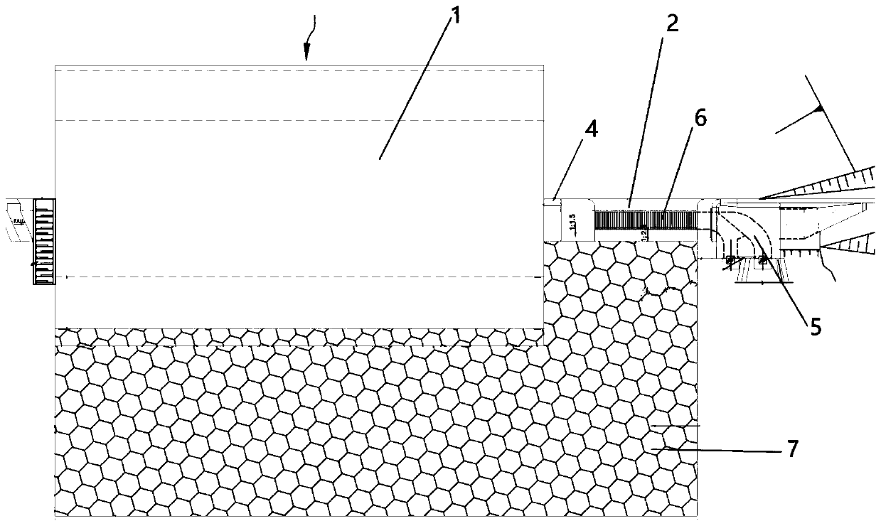
[0022] The water intake system of the water conservancy project is built on the river channel, and the water intake system includes an overflow weir 1, a water intake device, and a sand settling device arranged successively from one side of the river channel to the other side;

[0023] The overflow weir 1 is used for water storage and overflow flood discharge, and the downstream channel of the overflow weir 1 is provided with bottom protection 7;

[0024] The water intake device is a dam body structure arranged laterally along the river course, includi...


PUM


Abstract

The invention discloses a water intake system for a water conservancy project. The water intake system is constructed on a river channel, and comprises an overflow weir, a water intake device and a sand-settling device which are continuously arranged in sequence from one side to the other side of the river channel; the overflow weir is used for retaining water and overflow flood discharge, the water intake device is a dam structure horizontally arranged along the river channel, the water intake device comprises a retaining dam body at the front end surface, a water inlet at the top surface anda dam body at the rear end; the water inlet is arranged obliquely and downwards along the direction of the water flow, and a water inlet grill arranged obliquely and downwards along the direction ofthe water flow is arranged on the upper opening plane of the water inlet; the dam body of the water intake device is a hollow water channel, and the outlet of the water channel is connected with the inlet of the sand-settling device. The technical scheme of the invention adopts a water inlet to lead water directly, the water inlet grille is inclined downstream to facilitate the drainage of graveland realize the function of diversion and gravel drainage. The water intake system makes full use of the characteristics of small diversion flow of small-scale hydropower generation, and adopts a newmethod of diversion and drainage of gravel, so that a first hub is simpler and more practical, and the construction cost is reduced.

Description

technical field [0001] The invention belongs to the technical field of water conservancy engineering design, in particular to the technical field of water diversion engineering design in water conservancy engineering, in particular to a design of a water intake system for small-scale water diversion power generation or water diversion engineering. Background technique [0002] In small-scale hydropower projects in mountainous areas, the first hub usually adopts the gate dam method or the low dam water intake method. The main structures are retaining dams, sand washing gates, water intakes and grit chambers, and almost all water intakes use positive water intake. The direction of the inlet of the water intake is along the water flow, and the sand flushing gate adopts the method of flushing sand and gravel in the forward direction such as the bottom hole. exclusion. Contents of the invention [0003] According to the deficiencies of the prior art, the invention discloses a ...

Claims


Application Information

Patent Timeline
Patent Type & Authority Applications(China)
IPC IPC(8): E02B9/04E02B8/06E02B5/08
CPCE02B9/04E02B8/06E02B5/085Y02E10/20
Inventor 田雷刘政张建军
Owner SINOHYDRO BUREAU 7 CO LTD
Learn More