AC power flow linear sensitivity analysis method

A technology for sensitivity analysis and AC power flow, which is applied in the field of linear sensitivity analysis of AC power flow, and can solve problems such as impact

Pending Publication Date: 2019-12-03
GUANGDONG UNIV OF TECH
View PDF11 Cites 1 Cited by
  • Summary
  • Abstract
  • Description
  • Claims
  • Application Information

AI Technical Summary

Problems solved by technology

[0004] In order to solve the deficiency that the sensitivity analysis of the power system in the prior art only focuses on the influence of the

Method used


Image

  • AC power flow linear sensitivity analysis method
  • AC power flow linear sensitivity analysis method
  • AC power flow linear sensitivity analysis method

Examples


Embodiment 1

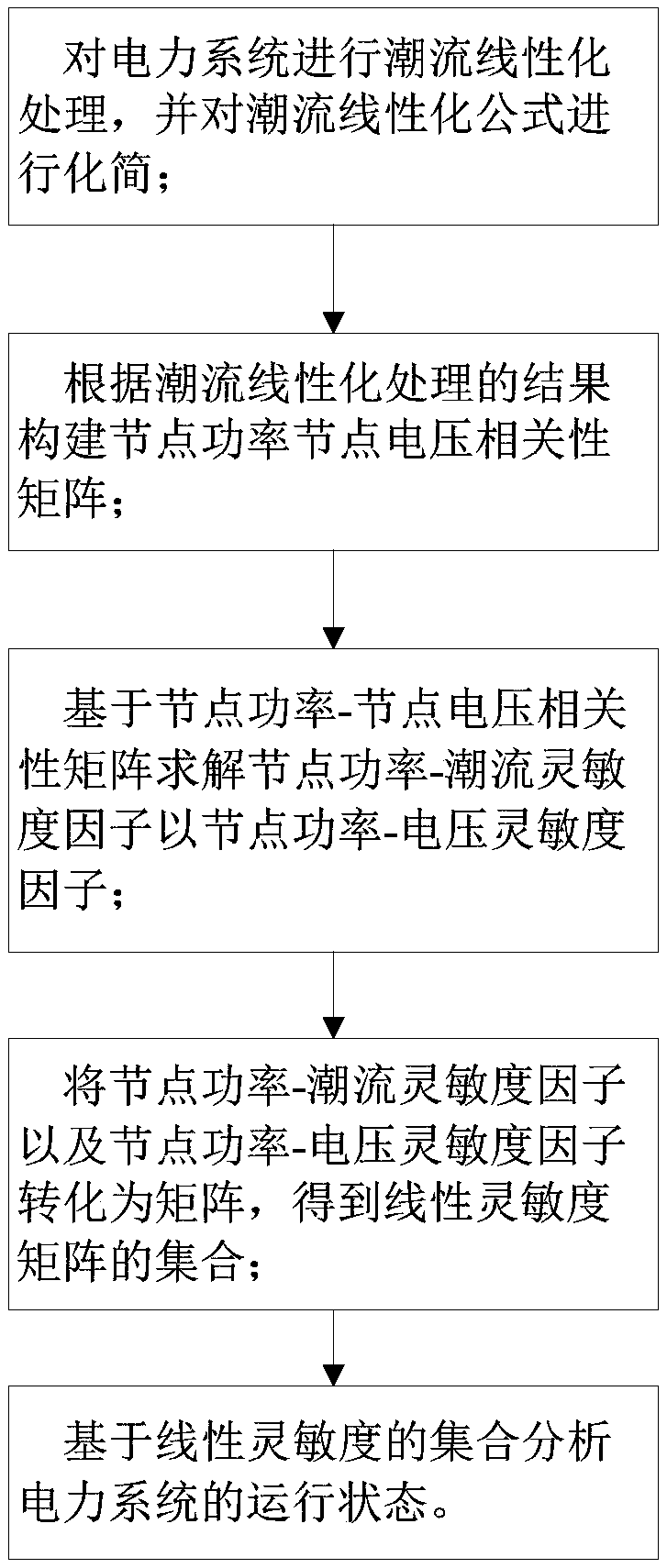
[0067] Such as figure 1 As shown, an AC power flow linear sensitivity analysis method includes the following steps:

[0068] Step S1: Perform power flow linearization processing on the power system, and simplify the power flow linearization formula;

[0069] Step S2: Construct a node power-node voltage correlation matrix according to the result of power flow linearization processing;

[0070] Step S3: Solve the node power-flow sensitivity factor and the node power-voltage sensitivity factor based on the node power-node voltage correlation matrix;

[0071] Step S4: Transform the node power-flow sensitivity factor and the node power-voltage sensitivity factor into a matrix to obtain a set of linear sensitivity matrices;

[0072] Step S5: Analyze the operating state of the power system based on the set of linear sensitivities.

[0073] Preferably, in step S3, the node power-node voltage sensitivity factor and the node power-voltage sensitivity factor are obtained by deriving n...


PUM


Abstract

The invention relates to the field of power analysis, in particular to an AC power flow linear sensitivity analysis method. Based on linearized power flow calculation and a node power-node voltage correlation matrix, a node power-power flow sensitivity factor and a node power-voltage sensitivity factor are obtained through derivation of node active power and node reactive power, the sensitivity factors are converted into a matrix form, and a linear sensitivity matrix is obtained. According to the linear sensitivity analysis method, linearized simplification is carried out on the basis of an ACpower flow equation, all original power flow variables are reserved through simplification, the accuracy of the linearized equation is guaranteed to the maximum extent, and power flow in the power system can be accurately and rapidly solved. The linear sensitivity analysis method provided by the invention contains a plurality of sensitivity factors, can be used for solving the problem of a powersystem based on linear programming, and realizes a more comprehensive and accurate power system optimization decision.

Description

technical field [0001] The invention relates to the field of electric power analysis, and more specifically, relates to an AC power flow linear sensitivity analysis method. Background technique [0002] With the vigorous development and gradual improvement of the power system, domestic and foreign researchers have carried out detailed analysis on the operation of the power system. [0003] In the field of power system sensitivity analysis, there are many research theories. In existing research results, power transmission allocation factors include SF (shift factor), DF (delivery factor, transmission factor), LF (loss factor, loss factor) and the like. In the analysis of the transfer factor, the past studies only focused on the influence of the active power injected by the node on the active power flow, and did not analyze the influence of the active power injected by the node on the reactive power flow, the reactive power injected by the node on the active power flow, and t...

Claims


Application Information

Patent Timeline
IPC IPC(8): H02J3/06
CPCH02J3/06
Inventor 李镇豪王逸飞赖来利
Owner GUANGDONG UNIV OF TECH
Why Eureka
Try Eureka