
Power control method, device and system

A technology of power control and power control parameters, applied in power management, transmission systems, digital transmission systems, etc., can solve problems such as long distances, large link differences, and insufficient flexibility

Pending Publication Date: 2019-12-03
ZTE CORP
View PDF4 Cites 24 Cited by
  • Summary
  • Abstract
  • Description
  • Claims
  • Application Information

AI Technical Summary

Problems solved by technology

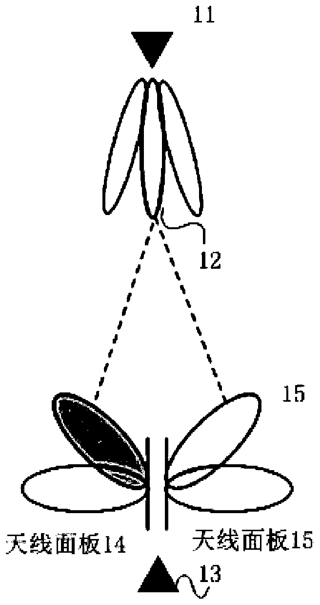
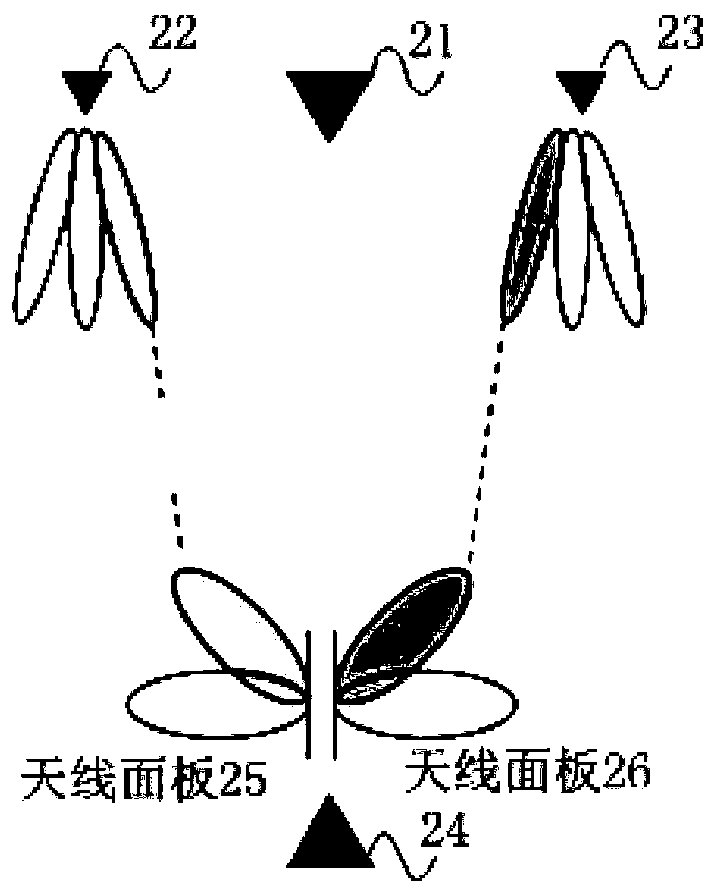
[0003] However, when the base station configures multiple TRPs, the physical locations of different TRPs may be far away, and the link between each TRP and user equipment (User Equipment, UE) is very different, and the power control between each TRP and UE should be independent. Yes, but in the existing power control mechanism, the number of power control parameters is small, and the flexibility is not enough in the application of multiple TRP scenarios

Method used


Image

  • Power control method, device and system
  • Power control method, device and system
  • Power control method, device and system

Examples


Embodiment Construction

[0040] Embodiments of the present application will be described in detail below in conjunction with the accompanying drawings.

[0041] The beam is an effective means for high-frequency communication to increase the transmission distance and avoid interference. The beam has directionality and width. In order to cover different directions, usually the sending end and the receiving end will configure multiple antennas to form beams in multiple directions.

[0042] The multiple antennas of a wireless communication node can be divided into different groups, and each group is called an antenna panel, also called an antenna panel, and referred to as a panel for short. Generally, UE can support multiple antenna panels, covering different directions respectively. Different antenna panels can generally transmit beams at the same time. One or more beams can be sent simultaneously on each antenna panel. The number of beams that can be transmitted simultaneously on each antenna panel i...


PUM


Abstract

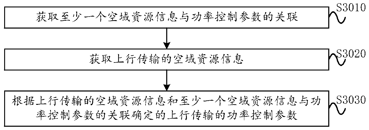
The invention provides a power control method, device and system. The power control method comprises the steps of obtaining association of at least one piece of airspace resource information and a power control parameter; acquiring airspace resource information of uplink transmission; determining a power control parameter of the uplink transmission according to the spatial domain resource information of the uplink transmission and the association of the at least one piece of spatial domain resource information and the power control parameter, wherein the airspace resource information comprisesat least one kind of CORESET information, TRP information and PUCCH resource information.

Description

technical field [0001] The present application relates to wireless communication networks, for example, to a power control method, device and system. Background technique [0002] In the next-generation mobile communication network, ultra-high speed is a key requirement, and a base station configured with multiple Transmitter Receiver Points (TRP) can meet the ultra-high speed requirement to a certain extent. When the base station is configured with multiple TRPs, on the one hand, the number of antennas can be increased; on the other hand, more links with large differences can be obtained because the multiple TRPs are in different physical locations, which can avoid signal blocking. [0003] However, when the base station configures multiple TRPs, the physical locations of different TRPs may be far away, and the link between each TRP and user equipment (User Equipment, UE) is very different, and the power control between each TRP and UE should be independent Yes, but in the...

Claims


Application Information

Patent Timeline
IPC IPC(8): H04W52/14H04W52/18H04W72/12H04L5/00
CPCH04W52/146H04W52/18H04W72/121H04W72/1268H04L5/0053H04W72/23H04W52/365H04W52/242H04W52/42H04L5/0023H04W72/046
Inventor 姚珂蒋创新高波鲁照华
Owner ZTE CORP
Learn More