Electric Vacuum Cleaner System

A vacuum cleaner, electric technology, applied in the installation of vacuum cleaners, suction filters, electrical equipment, etc., can solve problems such as unstable operation, and achieve the effect of suppressing reaction force

Active Publication Date: 2022-04-08
TWINBIRD CORP
View PDF9 Cites 0 Cited by
  • Summary
  • Abstract
  • Description
  • Claims
  • Application Information

AI Technical Summary

Problems solved by technology

[0006] However, in such an adapter, when using an extension tube as an accessory or using it without connecting an accessory, exhaust gas will be strongly ejected from the receiving cylinder part located at a position away from the gripping part. There is a possibility that the operation becomes unstable due to the reaction force of the exhaust gas

Method used


Image

  • Electric Vacuum Cleaner System
  • Electric Vacuum Cleaner System
  • Electric Vacuum Cleaner System

Examples


Embodiment Construction

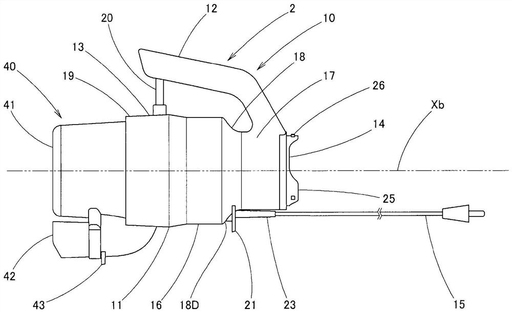
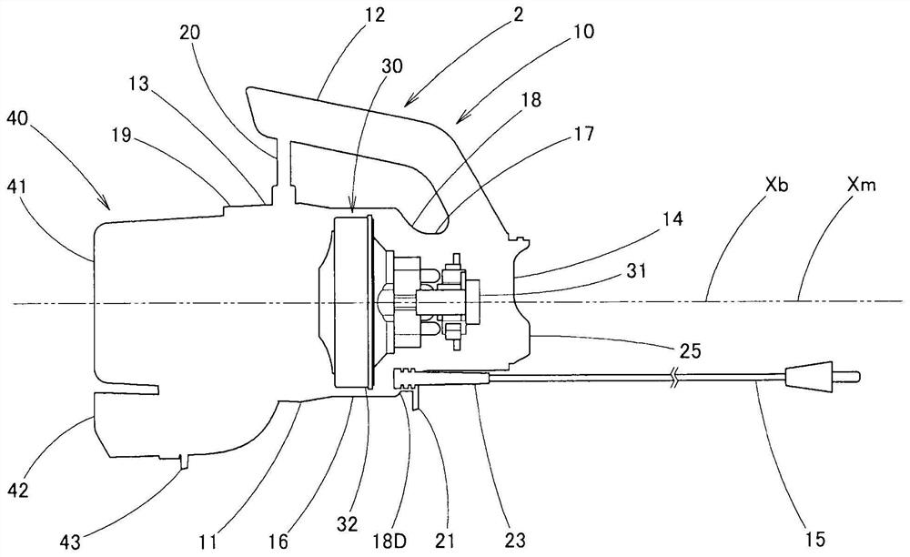
[0027] Below, based on Figure 1 to Figure 11 , the embodiment of the present invention will be described. Furthermore, in this embodiment, the figure 1 and figure 2 Set the left side as the front side, and the right side as the rear side. Additionally, the figure 1 and figure 2 The up and down in are set to the up and down in the following description. Reference numeral 1 is an electric vacuum cleaner system. This electric vacuum cleaner system 1 has an electric vacuum cleaner 2 , an exhaust utilization adapter 50 , and an exhaust attachment 60 .

[0028] The electric vacuum cleaner 2 has a vacuum cleaner main body 10 and a dust collection container 40 . The vacuum cleaner main body 10 has a body part 11 and a grip part 12 . The body portion 11 has a substantially cylindrical housing case 13 having portions with different diameters. Furthermore, the dust collecting container 40 is detachably attached to the front side of the body part 11 . In addition, an exhaust ...


PUM


Abstract

The present invention provides an electric vacuum cleaner system capable of suppressing the reaction force caused by the blown airflow of exhaust gas and operating stably. The electric vacuum cleaner system includes: an electric vacuum cleaner having a handle and an exhaust port; an exhaust utilization adapter having a mounting portion as an inlet with a relatively large flow area and a receiving cylinder as an outlet with a relatively small flow area part; and an exhaust attachment, wherein the installation part is connected to the exhaust port of the electric vacuum cleaner, the attachment is connected to the receiving tube part, and, in the state where the adapter is installed on the exhaust port part, the second center of the receiving tube part (X2) is provided so as to be eccentric to the grip portion side with respect to the first center (X1) of the mounting portion, whereby the ejection position of the exhaust gas can be set near the grip portion. Therefore, when using the jet air flow, It is possible to perform stable operation while suppressing the reaction force caused by the blown air flow.

Description

technical field [0001] The present invention relates to an electric vacuum cleaner system capable of blowing off dust by using the exhaust gas of the vacuum cleaner. Background technique [0002] Conventionally, such a vacuum cleaner system is known in which an adapter is attached to an exhaust port of a vacuum cleaner body having a grip and an accessory is connected to the adapter (for example, refer to Patent Document 1). In addition, the adapter has a mounting portion as a wide portion and a receiving cylinder portion as a narrow portion. In addition, the installation part and the receiving cylinder part are coaxial. In addition, a non-bendable extension tube or a bendable extension hose is used as an accessory attached to the receiving cylinder portion of the adapter. [0003] prior art literature [0004] patent documents [0005] Patent Document 1: Japanese Patent Laid-Open No. 2016-49141 [0006] However, in such an adapter, when using an extension tube as an acc...

Claims


Application Information

Patent Timeline
Patent Type & Authority Patents(China)
IPC IPC(8): A47L5/02A47L9/16A47L9/28
CPCA47L5/02A47L9/2836A47L9/28A47L9/1658
Inventor 反町干夫青木佳
Owner TWINBIRD CORP
Why Eureka
Try Eureka