Probes and Connection Fixtures

A technology for connecting fixtures and probes, which is applied in the direction of measuring devices, instruments, and measuring electronics. It can solve problems such as probe preload deviation and compression size deviation, and achieve the effect of suppressing reaction force and preventing deformation.

Active Publication Date: 2016-06-22
NIDEC-READ CORPORATION
View PDF7 Cites 0 Cited by
  • Summary
  • Abstract
  • Description
  • Claims
  • Application Information

AI Technical Summary

Problems solved by technology

However, in this structure, due to the influence of the variation in the length of the probes, the compressed size of each probe used for preloading varies, resulting in variation in the preloading of each probe

Method used


Image

  • Probes and Connection Fixtures
  • Probes and Connection Fixtures
  • Probes and Connection Fixtures

Examples


no. 1 approach

[0044]

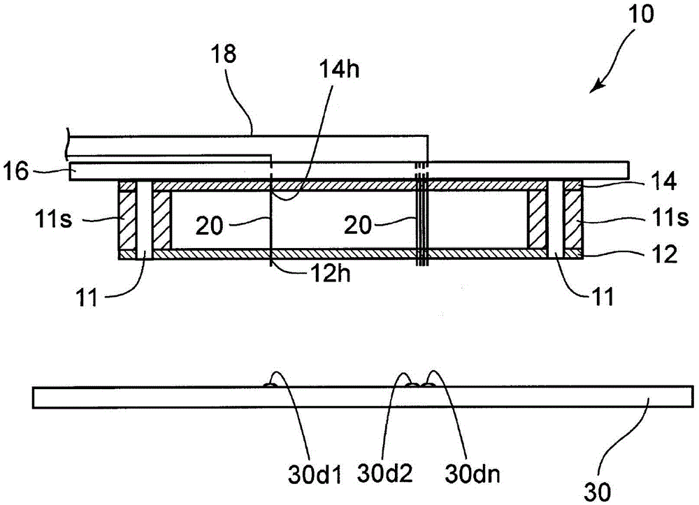
[0045] refer to figure 1 , the schematic configuration of the connection jig using the probe according to the first embodiment of the present invention will be described. The connection jig 10 includes a first probe holding member 12 , a second probe holding member 14 , and an electrode portion 15 (refer to Figure 5 ) and the electrode holding member 16. The first and second probe holding members 12 and 14 are formed of insulating plate-like members such as resin or ceramics. The first and second probe holding members 12 and 14 are held at a predetermined distance by the rod-shaped support member 11 and the spacer 11s attached around the rod-shaped support member 11 .

[0046] The first probe holding member 12 is formed with a plurality of through holes 12h corresponding to the first through holes according to the present invention, and the distal end portion of the probe 20 inserted into the plurality of through holes 12h and held is guided to a predetermined po...

no. 2 approach

[0086] refer to Figure 7 and Figure 8 , the probe according to the second embodiment of the present invention will be described. like Figure 7 and Figure 8 As shown, the probe 40 includes: an outer conductor 41 , an inner conductor 42 and a fixing portion 43 .

[0087] The outer conductor 41 is electrically conductive and has a substantially cylindrical form (cylindrical form in this embodiment). The inner conductor 42 is electrically conductive and has a substantially cylindrical shape (cylindrical shape in this embodiment), and has a sharp abutment end 42c at its front end 42a that abuts on a connection point of the inspection object. Such an inner conductor 42 is inserted into the outer conductor 41 in such a manner that its front end portion 42 a protrudes from the front end side of the outer conductor 41 and its rear end portion 42 b does not protrude from the rear end side of the outer conductor 41 , and the inner conductor 42 is in contact with the outer conduct...


PUM


Abstract

The present invention provides a probe which can effectively suppress the reaction force of the preload of the probe mounted on a connection jig without impairing the spring characteristics when it abuts against a connection point of an inspection object. In this probe (20), the outer conductor (22) is electrically conductive and has a substantially cylindrical form. The inner conductor (24) has conductivity, is inserted into the outer conductor (22), and is electrically connected to the outer conductor (22), and its front end (24a) abuts against a connection point of an inspection object. On the peripheral wall of the outer conductor (22), a first spring part (221) with a smaller spring constant is located on the front end side of the second spring part (222), and is provided with a spring that expands and contracts in the axial direction of the probe (20). The first and second spring parts (221), (222) having different spring constants. The fixing part (26) fixes the middle part (22c) between the first spring part (221) and the second spring part (222) of the outer conductor (22) and the inner conductor (24).

Description

technical field [0001] The present invention relates to a probe and a connection jig. The probe is used in a connection jig for electrical connection with a connection point provided on an inspection object. Background technique [0002] Such a connection jig is called, for example, an inspection jig or an inspection card, and has a plurality of probes, through which a current or an electric signal from an inspection device or the like is supplied to a connection point set in advance on the inspection object, and detection is performed from the connection point. The electrical characteristics between the connection points are detected by the output signal, and the operation test of the continuity check or the leakage check is performed. [0003] As the inspection objects, there are printed wiring boards, flexible boards, ceramic multilayer wiring boards, electrode plates for liquid crystal displays or plasma displays, various substrates such as packaging substrates for semic...

Claims


Application Information

Patent Timeline
Patent Type & Authority Patents(China)
IPC IPC(8): G01R1/067G01R1/04
CPCG01R1/06722G01R1/06733G01R1/07371G01R31/2886
Inventor 太田宪宏
Owner NIDEC-READ CORPORATION
Why Eureka
Try Eureka