A new technique for dismantling coupling keys with liquid nitrogen

A technology of coupling and new technology, applied in metal processing, manufacturing tools, metal processing equipment, etc., can solve the problems of difficult disassembly of keys and keyways, scratches on the inner wall of keyways, etc. The effect of the probability of occurrence

Active Publication Date: 2021-04-16
成都中车四方轨道车辆有限公司
View PDF10 Cites 0 Cited by
  • Summary
  • Abstract
  • Description
  • Claims
  • Application Information

AI Technical Summary

Problems solved by technology

[0004] Aiming at the problem that the key and keyway of the gearbox coupling in the prior art are difficult to disassemble and the inner wall of the keyway is easily scratched during the disassembly process, the present invention provides a new process for disassembling the coupling key with liquid nitrogen, the purpose of which is to : After the coupling key is corroded, the key can be disassembled without damaging the keyway and key, improving the qualified rate of operation

Method used


Image

  • A new technique for dismantling coupling keys with liquid nitrogen
  • A new technique for dismantling coupling keys with liquid nitrogen
  • A new technique for dismantling coupling keys with liquid nitrogen

Examples


Embodiment 1

[0028] This embodiment includes the following steps:

[0029] [1] Separate the small shaft of the gearbox from the coupling, and leave the key in the keyway on the side of the coupling;

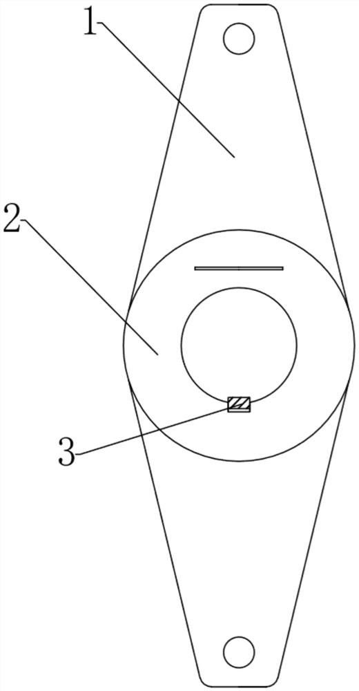
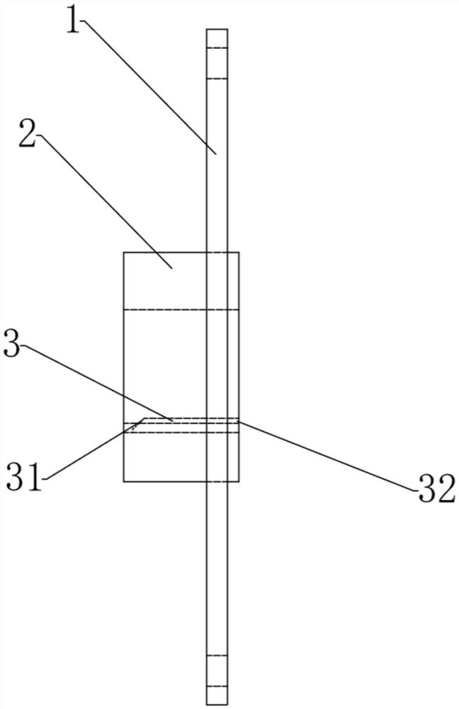
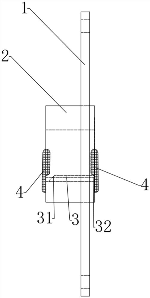
[0030] [2] The fence made of non-drying putty is used to seal the two ends of the coupling, and the fence is as follows image 3 As shown, they are respectively located at both ends of the through hole of the main body of the coupling, and the enclosure part blocks the through hole, so that the inner wall of the through hole and the enclosure form a frame-shaped space together; on the circumference of the edge of the through hole, the key and keyway It should be located within the range blocked by the enclosure so that the key and keyway are located in the box-shaped space;

[0031] [3] Pour liquid nitrogen into the frame-shaped space through the unblocked part of the through hole to soak the key and keyway. The preferred time for soaking the key and keyway in liquid nitrogen is 20-40S. If ...

Embodiment 2

[0033] This embodiment includes the following steps:

[0034] [1] Separate the small shaft of the gearbox from the coupling, and leave the key in the keyway on the side of the small shaft of the gearbox;

[0035] [2] Use non-drying putty to make a fence on the shaft extension end of the small shaft of the gearbox, so that the non-drying putty and the gearbox together form a frame-shaped space with an opening upward, so that the key and keyway are located in the frame-shaped space , for example, the frame-shaped space can be made into shapes such as strips, ellipses, or cuboids;

[0036] [3] Pour liquid nitrogen into the frame-shaped space through the upper opening of the frame-shaped space to soak the key and keyway. The preferred time for soaking the key and keyway in liquid nitrogen is 20-40S. If the liquid nitrogen evaporates or leaks within this time If it is reduced, liquid nitrogen should be replenished in time to keep the key and keyway in liquid nitrogen; after soakin...


PUM


Abstract

The invention belongs to the technical field of rail transit equipment, and relates to the maintenance of subway vehicles, in particular to a new process for dismantling coupling keys with liquid nitrogen. Aiming at the problem in the prior art that the key and keyway of the gear box coupling are corroded, it is difficult to disassemble and the inner wall of the keyway is easily scratched during the disassembly process, the technical solution of the present invention is: use non-drying putty on the small shaft of the gearbox The end of the shaft extension is framed or sealed at both ends of the coupling to form a frame-shaped space. After liquid nitrogen is poured into the frame-shaped space, the soaking time of the key and keyway is extended to take advantage of the inherent thermal expansion and contraction of the metal. The principle is to make a small gap between the key and the keyway, so that the key can be removed. This scheme can effectively prevent the key and the keyway from being scratched, and improve the qualification rate of the operation.

Description

technical field [0001] The invention belongs to the technical field of rail transit equipment, and relates to the maintenance of subway vehicles, in particular to a new process for dismantling coupling keys with liquid nitrogen. Background technique [0002] In the urban rail vehicle maintenance industry, the gearbox coupling adopts a key and keyway structure. When disassembling, most of them use direct knocking to disassemble and remove the key. This process is widely used. [0003] Since the coupling of the subway vehicle needs to be disassembled during the overhaul of the frame, the coupling keys are corroded, painted, and the keys are stuck due to force, which makes it difficult to remove the key from the keyway. The knocking method is used for disassembly It is easy to cause scratches on the inner wall of the keyway. If the scratches are serious, the shaft head and the key must be replaced. In view of the corrosion of the key and the keyway, there is a problem that the...

Claims


Application Information

Patent Timeline
Patent Type & Authority Patents(China)
IPC IPC(8): B23P11/02
CPCB23P11/02B23P11/025
Inventor 翟好璟张仕华康小雪彭华
Owner 成都中车四方轨道车辆有限公司
Why Eureka
Try Eureka