Material taking and conveying mechanism, lifting and conveying mechanism and multi-layer circulating intelligent conveying system

A transmission mechanism and multi-layer circulation technology, which is applied in the direction of conveyors, conveyor objects, transportation and packaging, etc., can solve problems that have not been widely used in other fields, affect transportation efficiency, and damage to cargo accumulation, so as to reduce the structure of the device The effect of increasing complexity, improving operational stability, and saving manufacturing costs

Pending Publication Date: 2019-12-06
SHANDONG UNIV
View PDF0 Cites 3 Cited by
  • Summary
  • Abstract
  • Description
  • Claims
  • Application Information

AI Technical Summary

Problems solved by technology

[0002] All kinds of production and living fields need conveying equipment that can lift materials to a specified height. Most of the existing multi-layer conveying systems use conveyor belts to convey obliquely upwards, which not only takes up a lot of space, but also tends to cause problems such as accumulation and damage of goods.
Traditional hoists are mos

Method used


Image

  • Material taking and conveying mechanism, lifting and conveying mechanism and multi-layer circulating intelligent conveying system
  • Material taking and conveying mechanism, lifting and conveying mechanism and multi-layer circulating intelligent conveying system
  • Material taking and conveying mechanism, lifting and conveying mechanism and multi-layer circulating intelligent conveying system

Examples


Embodiment 1

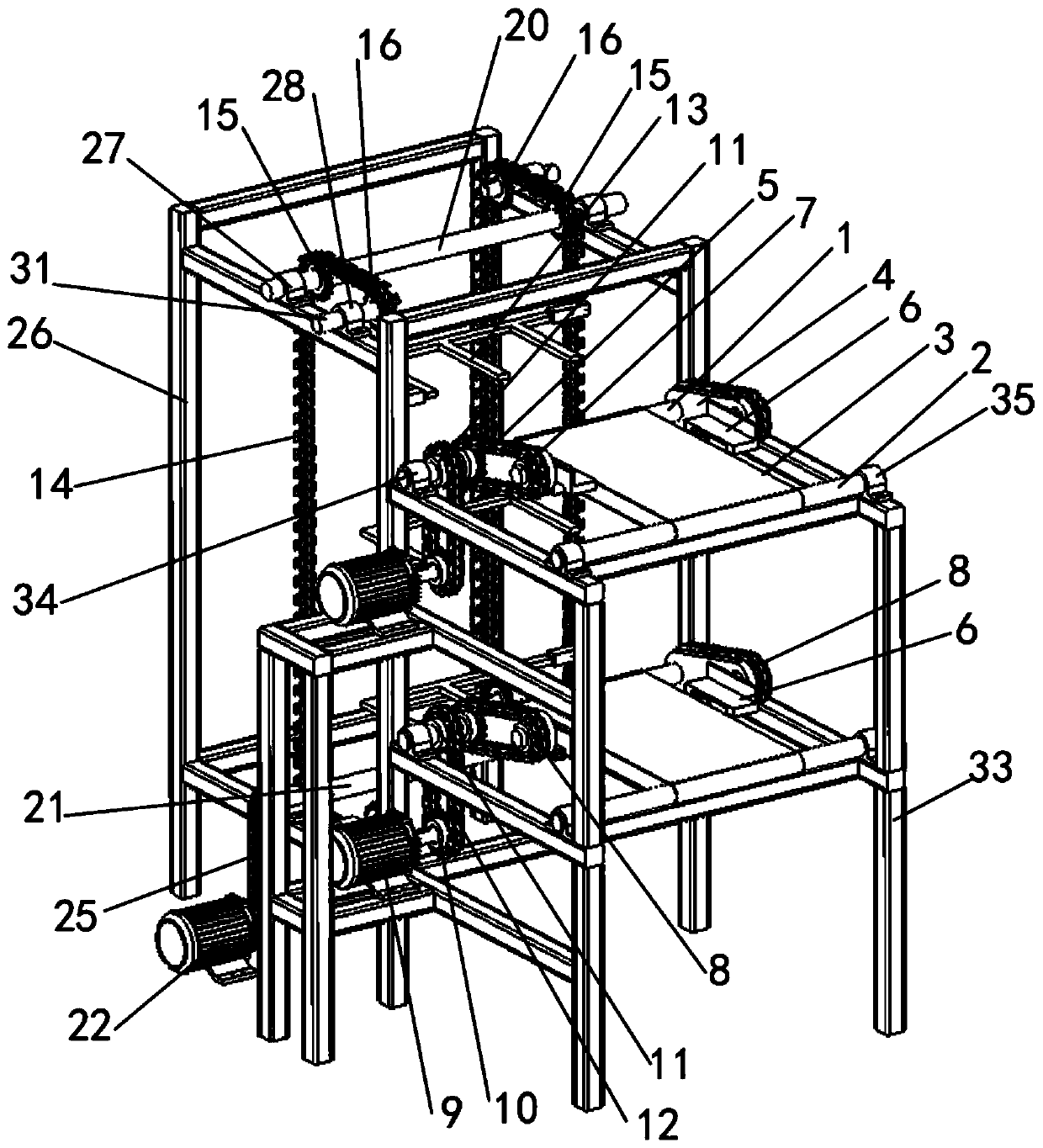
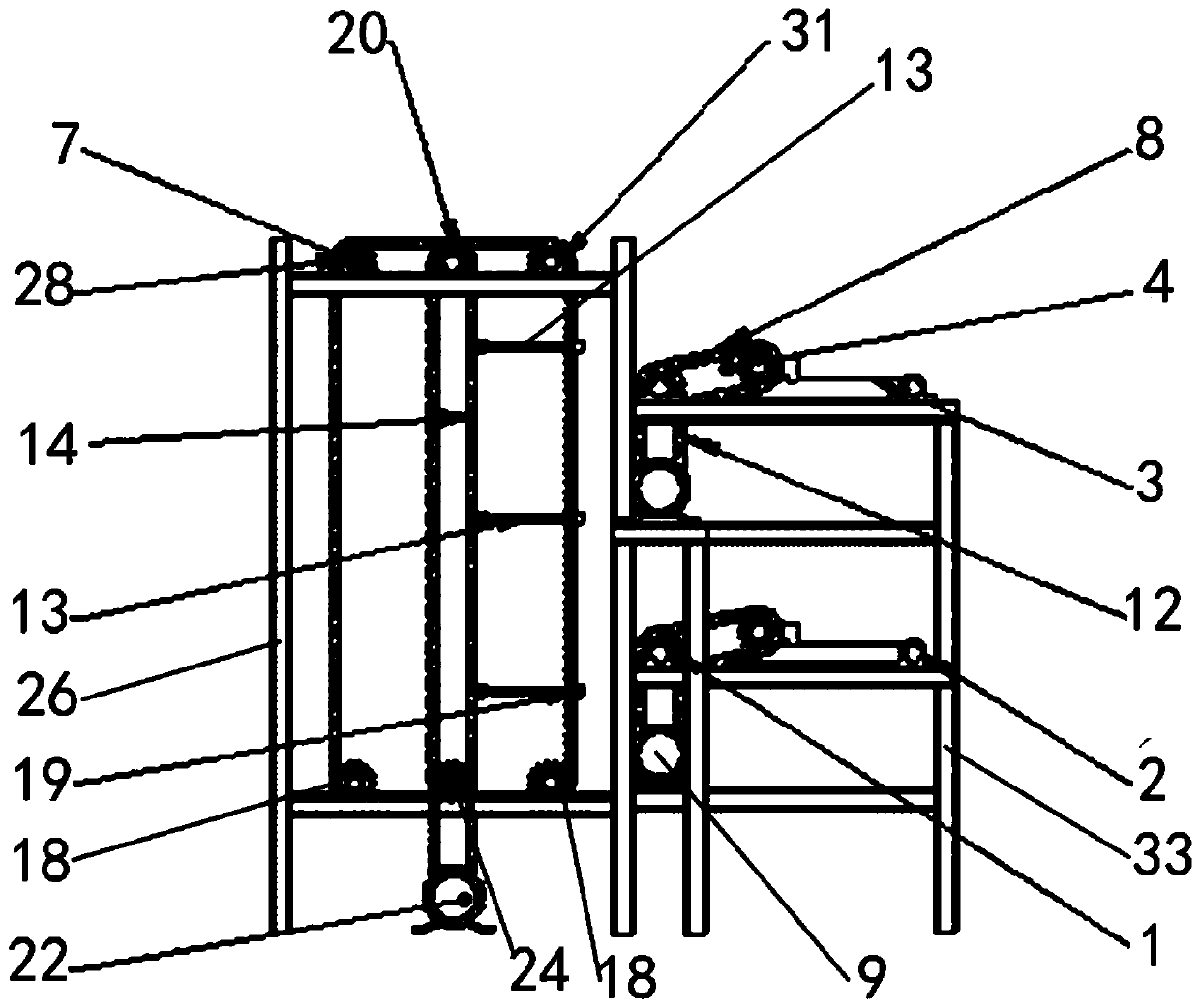
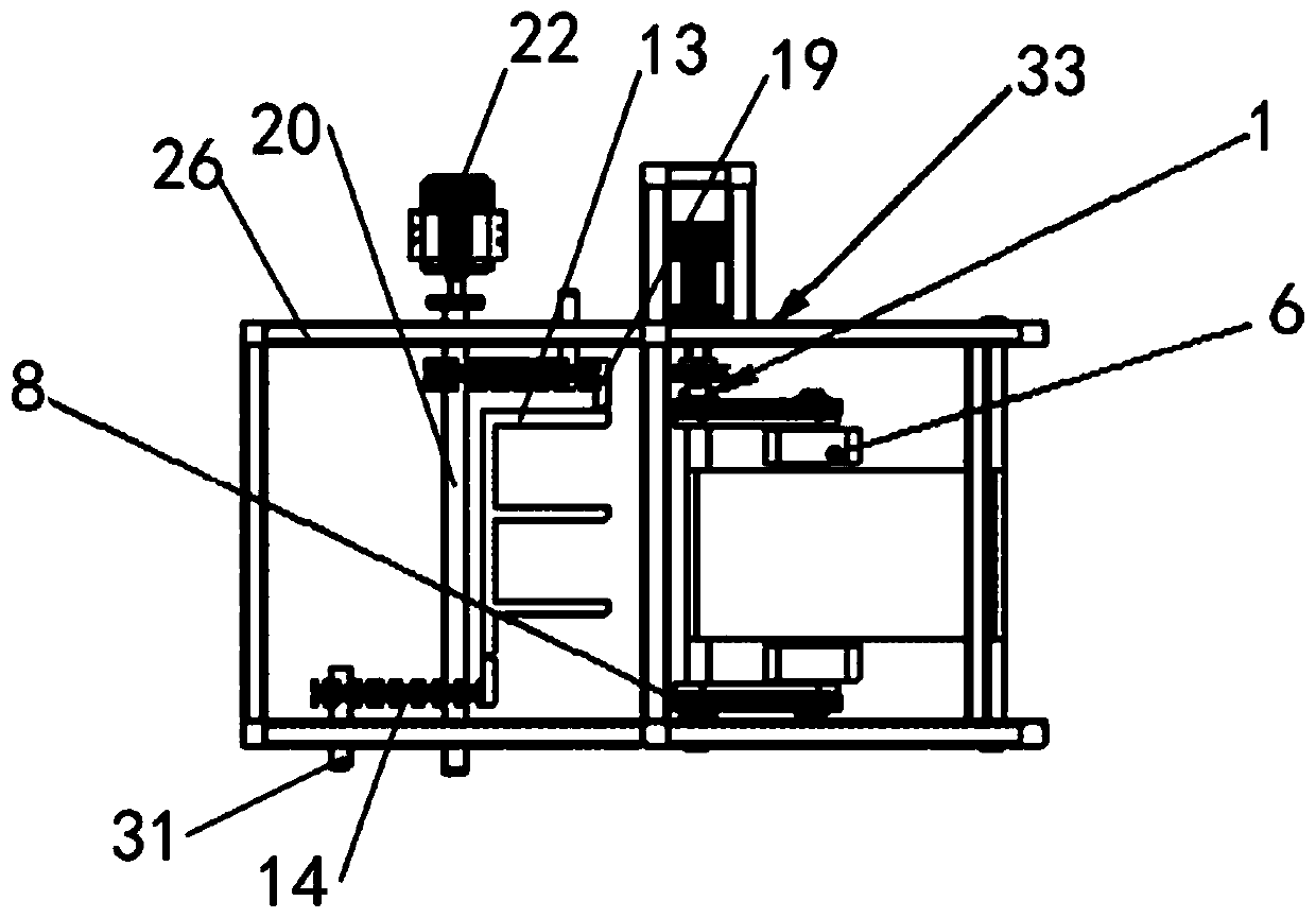
[0044] Such as Figure 1-Figure 4 As shown, the present embodiment provides a pick-up transmission mechanism, including a pick-up driving shaft 1, a pick-up driven shaft 2 and a pick-up drive mechanism connected to the pick-up drive shaft 1, a pick-up drive shaft 1 and a pick-up drive shaft. A conveyor belt 3 is arranged between the driven shafts 2; a pick-up arm 4 and a pick-up drive sprocket 5 are installed on the pick-up drive shaft 1, and a tray drive assembly is provided at the end of the pick-up arm 4; the tray drive assembly includes a tray 6 And the fetching driven sprocket 7, between the tray 6 and the fetching driven sprocket 7, a linkage shaft is arranged, the linkage shaft and the fetching arm 4 rotate and cooperate, and the fetching driving sprocket 5 and the fetching driven sprocket 7 Be provided with fetching chain 8 between.

[0045] Since there is a conveyor belt 3 between the fetching driving shaft 1 and the fetching driven shaft 2, when the fetching driving...

Embodiment 2

[0050] This embodiment is optimized and defined on the basis of the above-mentioned embodiment 1.

[0051] In order to improve the smooth effect of fetching objects, two fetching arms 4 and two fetching driving sprockets 5 are symmetrically arranged on the fetching driving shaft 1 .

[0052] Concretely, two pick-up driving sprockets 5 are positioned at the outsides of two pick-up arms 4, pick-up driven sprockets 7 and tray 6 are respectively arranged on the outside and inside of pick-up arms 4, and pick-up chains 8 are positioned at the pick-up arm 4. The outer side of the object arm 4.

Embodiment 3

[0054] A lifting transmission mechanism, comprising two oppositely arranged transmission assemblies, a plurality of racks 13 installed on the transmission assemblies and a transmission drive mechanism for driving the transmission assemblies, the transmission assembly includes a sprocket and a chain meshed with the sprocket 14. The sprocket includes an upper transmission sprocket and a lower transmission sprocket. The upper transmission sprocket includes an upper main transmission sprocket 15 and an upper slave transmission sprocket 16. The two upper slave transmission sprockets 16 are respectively arranged on two upper main transmission sprockets. On both sides of the line between the sprocket wheels 15, the lower transmission sprocket includes the following main transmission sprocket and the lower slave transmission sprocket 18, and the two lower slave transmission sprockets 18 are respectively arranged between the two lower main transmission sprockets The both sides of the co...


PUM


Abstract

The invention relates to the technical field of intelligent lifting and circulating conveying systems, and discloses a material taking and conveying mechanism, a lifting and conveying mechanism and amulti-layer circulating intelligent conveying system. The material taking and conveying mechanism comprises a material taking driving shaft, a material taking driven shaft and a material taking drivemechanism in transmission connection with the material taking driving shaft. A conveying belt is arranged between the material taking driving shaft and the material taking driven shaft. Material taking arms and material taking driving chain wheels are mounted on the material taking driving shaft. A tray transmission assembly is arranged at the ends of the material taking arms. According to the material taking and conveying mechanism, the lifting and conveying mechanism and the multi-layer circulating intelligent conveying system, the aims of cargo conveying and taking between positions at different heights can be achieved, it is guaranteed that cargoes are taken and conveyed out in time, and the situation that economic losses are caused by cargo accumulation is avoided; and the design layout of the structure is greatly simplified, the transfer efficiency of a device is improved, resource consumption is greatly reduced, and therefore the work efficiency is greatly improved.

Description

technical field [0001] The invention relates to the technical field of intelligent lifting circulation conveying system, in particular to an object fetching and conveying mechanism, a lifting and conveying mechanism and a multi-layer circulating intelligent conveying system. Background technique [0002] All kinds of production and living areas require conveying equipment that can lift materials to a specified height. Most of the existing multi-layer conveying systems use conveyor belts to carry them obliquely upward, which not only takes up a lot of space, but also tends to cause problems such as accumulation and damage of goods. Traditional hoists are mostly used in mines and construction sites, but have not been widely used in other fields. At the same time, the existing recycling machine only has the function of recycling transportation, and the pick-up and delivery of objects must be done manually, which not only wastes manpower and material resources, but also greatly ...

Claims


Application Information

Patent Timeline
IPC IPC(8): B65G47/52B65G17/12B65G17/34B65G17/38
CPCB65G17/12B65G17/34B65G17/38B65G47/52
Inventor 王延刚郭鹏宁常皓何巧林王金帅李方琰葛晨宇
Owner SHANDONG UNIV
Why Eureka
Try Eureka