
Thin mutual reservoir description method taking reconstructed sand-to-ground ratio as seismic description target

A technology of sand-ground ratio and reservoir, applied in the field of thin inter-reservoir description, which can solve problems such as inability to peel off

Active Publication Date: 2019-12-06
CHINA PETROLEUM & CHEM CORP +1
View PDF6 Cites 2 Cited by
  • Summary
  • Abstract
  • Description
  • Claims
  • Application Information

AI Technical Summary

Problems solved by technology

The two relevant literatures retrieved above both regard the sand-to-ground ratio as the target of seismic description, and the sand-to-ground ratio only reflects the thickness attribute in the vertical direction of the reservoir, without lithology information, and whether the seismic attributes are single or combined, Not only the volume attribute but also the lithology attribute are contained in it, and the two attributes cannot be separated. Therefore, it is not enough to seek the correlation between the two and only start from the seismic aspect. It is necessary to reconstruct the sand-ground ratio. It is a feasible method to seek the high correlation between the two

Method used


Image

  • Thin mutual reservoir description method taking reconstructed sand-to-ground ratio as seismic description target
  • Thin mutual reservoir description method taking reconstructed sand-to-ground ratio as seismic description target
  • Thin mutual reservoir description method taking reconstructed sand-to-ground ratio as seismic description target

Examples


Embodiment Construction

[0043] In order to make the above and other objects, features and advantages of the present invention more comprehensible, the preferred embodiments are listed below and shown in the accompanying drawings in detail as follows.

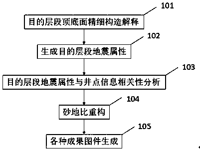
[0044] like figure 1 as shown, figure 1 It is a flow chart of the thin interreservoir description method with reconstructed sand-ground ratio as the seismic description target of the present invention.

[0045] Taking the research on the rolling evaluation of glutenite in the third sand formation of the fourth member of the Shahejie Formation in block A as an example, the implementation process of a description method for thin interbedded reservoirs with reconstructed sand-ground ratio as the seismic description target is illustrated.

[0046] Step 101, fine seismic structural interpretation of the top and bottom surfaces of the sand layer group. It is necessary to collect geological stratification data down to the sand group, calibrate the geologica...


PUM


Abstract

The invention provides a thin mutual reservoir description method taking a reconstructed sand-to-ground ratio as a seismic description target. The method comprises steps of S1, explaining fine seismicstructures of top and bottom surfaces of a sand layer group; S2, generating a plurality of seismic attribute bodies by applying seismic means; S3, analyzing the correlation between the various seismic attributes and a sand-to-ground ratio and a net-to-gross ratio, determining whether the correlation has zoning or not, and selecting the seismic attributes with high correlation in zones for subsequent research; S4, respectively reconstructing the sand-to-ground ratio according to the zones in the S3, calculating the correlation between the reconstructed sand-to-ground ratio and the net-to-grossratio and the optimal seismic attributes, and giving a linear formula; S5, making an optimized seismic attribute planar graph, and converting the seismic attribute planar graph into a reconstructed sand-to-ground ratio or net-to-gross ratio planar distribution graph by utilizing the formula in the S4; and S6, deriving a sand-to-ground ratio and net-to-gross ratio planar graph by utilizing the reconstructed sand-to-ground ratio and net-to-gross ratio planar graph. The method is advantaged in that the reconstructed sand-to-ground ratio is utilized as the seismic description target, so the reconstructed sand-to-ground ratio and the seismic attributes have high similarity, the distribution rule of a thin mutual reservoir is effectively described, and the rule can effectively guide explorationand development practices.

Description

technical field [0001] The invention relates to the field of petroleum and natural gas industry, in particular to a method for describing thin interbedded reservoirs with reconstructed sand-ground ratio as the seismic description target. Background technique [0002] Thin interbedded reservoirs have the characteristics of thin single layer, thin mudstone interlayer (the thickness of single layer is smaller than the seismic time and waveform can be distinguished), and the distribution of reservoirs is characterized by long intervals. In the Shengli Oilfield, a variety of sedimentary types will show the characteristics of thin inter-reservoirs, such as beach bar sand, turbidite, etc. These reservoirs are currently low in development and widely distributed, which is the basis for increasing reserves and production in the Shengli Oilfield in the future. important position. At present, the emerging reservoir description methods are mostly based on seismic methods, such as seismi...

Claims


Application Information

Patent Timeline
IPC IPC(8): G01V1/30
CPCG01V1/306G01V2210/624
Inventor 曲全工杜玉山张欣崔晓朵吴志华王筱文乌洪翠张德武庄绪超苗明
Owner CHINA PETROLEUM & CHEM CORP
Learn More