
Convenient assembling auxiliary tool for case and stator of servo motor

A technology for assembling auxiliary and servo motors, applied in electromechanical devices, manufacturing motor generators, manufacturing stator/rotor bodies, etc., can solve problems such as unfavorable press fitting, no tooling guarantee, stator misalignment or deformation, etc. The work is labor-saving and convenient, the positioning accuracy is reliable, and the work efficiency is improved.

Active Publication Date: 2019-12-06
HENAN NORMAL UNIV
View PDF10 Cites 2 Cited by
  • Summary
  • Abstract
  • Description
  • Claims
  • Application Information

AI Technical Summary

Problems solved by technology

[0002] The servo motor is mainly composed of casing, stator, rotor, end cover and other components. The stator is installed into the casing through interference fit. Usually, the assembly of the casing and the stator needs to be completed by shrink fitting. In the prior art, first Put the stator on the press and fix it, then put the casing into the oven and heat it to a certain temperature (the temperature is calculated according to the design value of the interference), and the workers put on heat-insulating gloves to quickly take out the casing and place it in the The stator is aligned and placed, and finally the press completes the pressing of the casing. During this process, there are the following problems: First, because the current servo motor stator basically adopts the splicing structure of split stators, that is, multiple split stators are spliced ​​to form Complete cylindrical stator, the existing stator fixing method

Method used


Image

  • Convenient assembling auxiliary tool for case and stator of servo motor
  • Convenient assembling auxiliary tool for case and stator of servo motor
  • Convenient assembling auxiliary tool for case and stator of servo motor

Examples


Embodiment

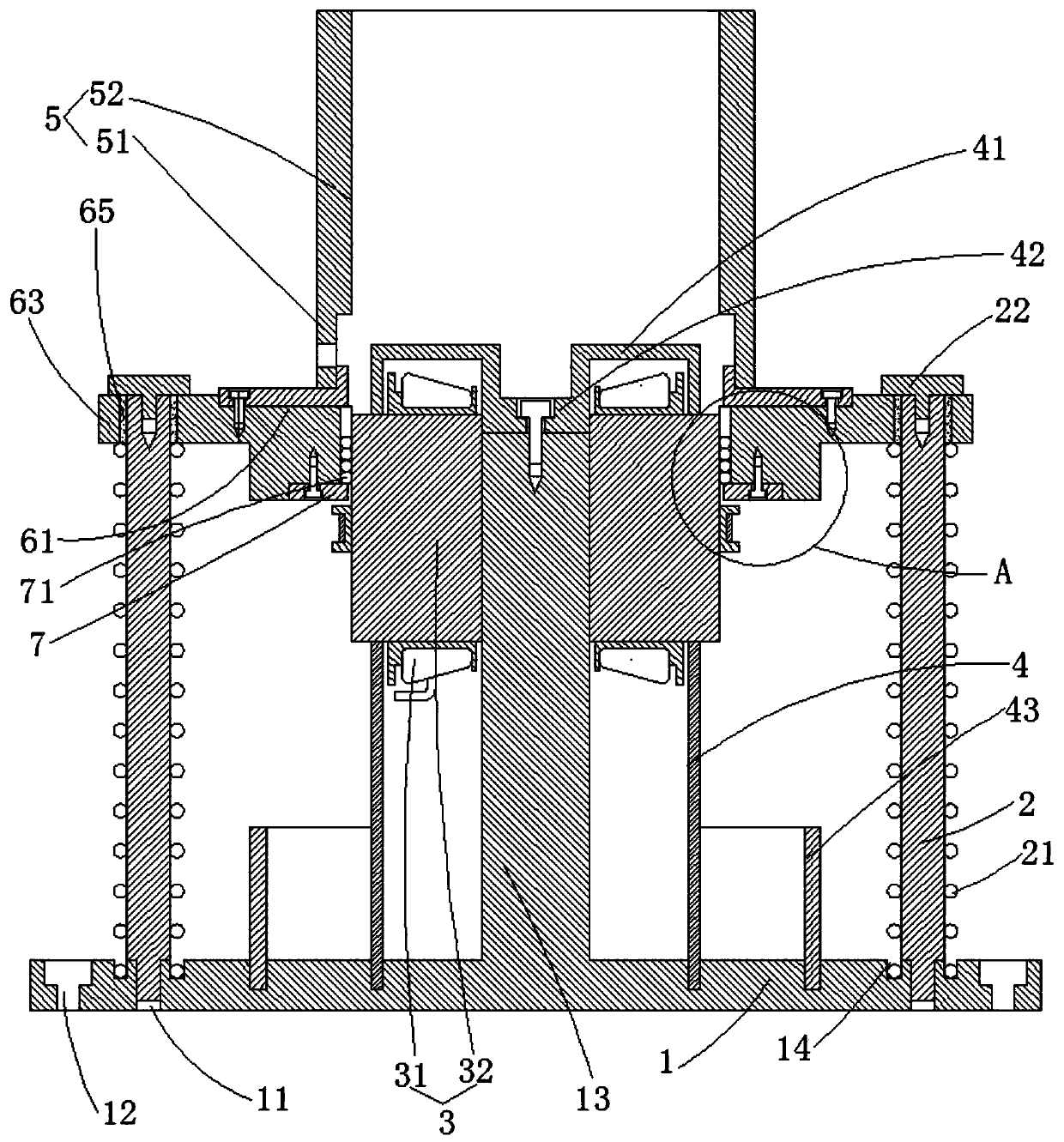
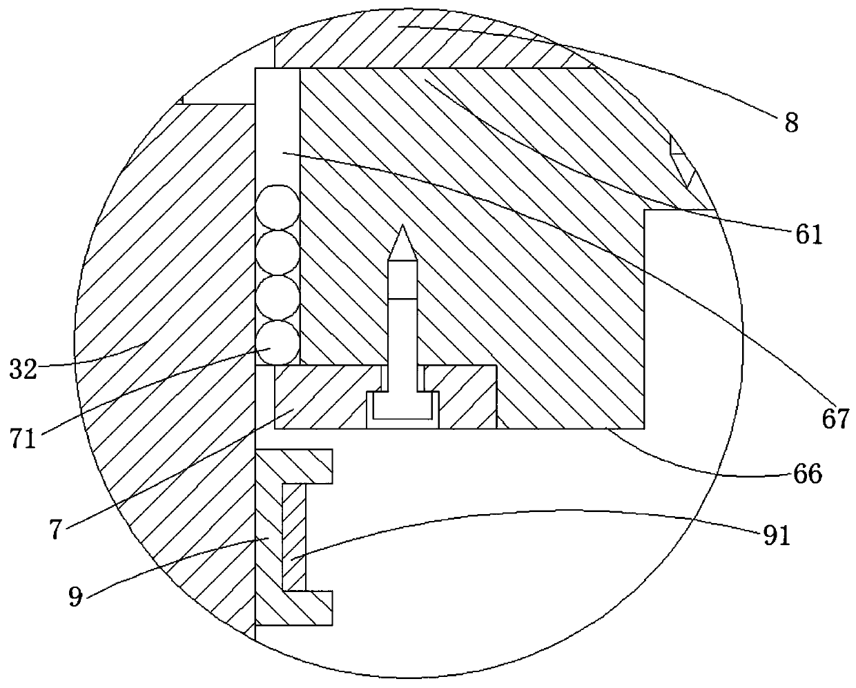
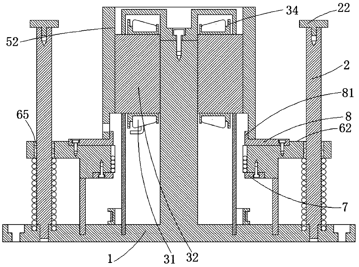
[0025] Such as Figure 1-Figure 10 As shown, a convenient assembly auxiliary tooling for the casing and stator of a servo motor includes a base 1, a guide rod 2, a support ring 4, a positioning ring 43 and a guide ring 6, and the upper end of the base 1 is symmetrically connected with a guide rod 2. The base 1 is provided with a base screw hole 11, the bottom end of the guide rod 2 is a threaded section and the outer diameter of the threaded section is smaller than the outer diameter of the upper part of the guide rod 2, and the bottom end of the guide rod 2 is screwed into the base screw hole 11 Until the upper end surface of the base 1 fits the step portion at the lower end of the guide rod 2 .

[0026] The base 1 is located on the periphery of the base screw hole 11 and is evenly distributed around the base mounting counterbore 12, and the base 1 can be installed and fixed by screwing screws in the base mounting counterbore 12.

[0027] The center of the upper end face of ...


PUM


Abstract

The invention discloses a convenient assembling auxiliary tool for a case and a stator of a servo motor. The tool comprises a base, a guide rod, a support ring, a positioning ring and a guide ring; the upper end of the base is connected with the guide rod, and a base convex column is arranged at the upper end of the base; the support ring and the positioning ring are mounted at the upper end of the base; the outer wall of the base convex column is attached to a stator. The guide ring comprises a mounting table, and arc-shaped through holes are uniformly distributed in the inner wall of the mounting table; balls are attached to the interiors of the arc-shaped through holes. A gland is mounted at the lower end of the mounting table, the balls are exposed out of the arc-shaped through holes,and abut against the stator, and the upper end of the mounting table is provided with a heat insulation ring, wherein the gland and the arc-shaped through holes limit the balls between the gland and the heat insulation ring; the heat insulation ring abuts against the case, and the case comprises a second case body; a sliding sleeve is attached to the outer wall of the stator, and a hoop is attached to the outer wall of the sliding sleeve; and the case is pressed downwards to enable the second case body to be pressed in interference fit. According to the invention, the stator is fixed reliablyand firmly, the temperature of the case cannot be reduced rapidly, and the case and the stator are assembled accurately and reliably with high efficiency.

Description

technical field [0001] The invention relates to the field of assembly tooling for motor parts, and more specifically relates to a convenient assembly auxiliary tooling for a casing and a stator of a servo motor. Background technique [0002] The servo motor is mainly composed of casing, stator, rotor, end cover and other components. The stator is installed into the casing through interference fit. Usually, the assembly of the casing and the stator needs to be completed by shrink fitting. In the prior art, first Put the stator on the press and fix it, then put the casing into the oven and heat it to a certain temperature (the temperature is calculated according to the design value of the interference), and the worker puts on the heat-insulating gloves to quickly take out the casing and place it in the The stator is aligned and placed, and finally the press presses down the casing. During this process, there are the following problems: First, because the current servo motor st...

Claims


Application Information

Patent Timeline
IPC IPC(8): H02K15/00H02K15/02H02K15/14
CPCH02K15/00H02K15/028H02K15/14
Inventor 吴喜桥王立林果
Owner HENAN NORMAL UNIV
Learn More