
Contact vibration detection device, rotating machine provided with same, and contact vibration detection method

A technology of contact vibration and detection device, which is applied in the field of rotating machinery and can solve the problems of inability to detect contact vibration and lack of vibration detectors.

Active Publication Date: 2019-12-06
MITSUBISHI HEAVY IND LTD
View PDF8 Cites 0 Cited by
  • Summary
  • Abstract
  • Description
  • Claims
  • Application Information

AI Technical Summary

Problems solved by technology

However, in relatively small rotating machines, vibration detectors may not be provided
Therefore, in this case, the technique described in the above-mentioned Patent Document 1 cannot detect the contact vibration.

Method used


Image

  • Contact vibration detection device, rotating machine provided with same, and contact vibration detection method
  • Contact vibration detection device, rotating machine provided with same, and contact vibration detection method
  • Contact vibration detection device, rotating machine provided with same, and contact vibration detection method

Examples


Embodiment Construction

[0044] Hereinafter, several embodiments of the present invention will be described with reference to the drawings. However, the following contents described as the embodiments or the contents described in the drawings are merely examples, and can be arbitrarily changed and implemented without departing from the gist of the present invention. In addition, each embodiment can be implemented in any combination of two or more. In addition, in each embodiment, the same reference numerals are given to common components, and redundant descriptions are omitted in order to simplify the description.

[0045] In addition, the dimensions, materials, shapes, and relative arrangements of the components described in the embodiments or shown in the drawings are not intended to limit the scope of the present invention to these, and are merely illustrative examples.

[0046] For example, expressions such as "in a certain direction", "along a certain direction", "parallel", "orthogonal", "center", "...


PUM


Abstract

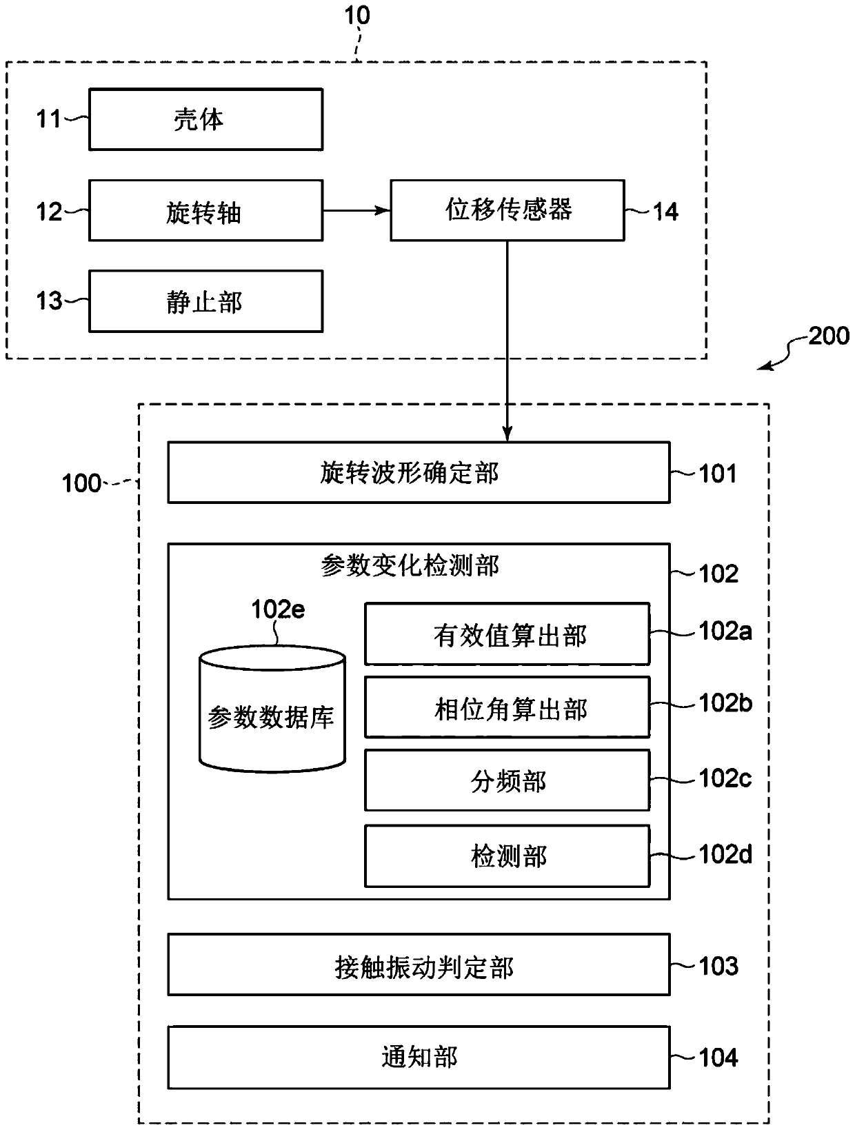
A contact vibration detection device 100 is for detecting contact vibration resulting from the contact of a stopping part 13 with a rotating shaft 12. The contact vibration detection device 100 comprises a rotation waveform determination unit 101 for determining a rotation waveform for the rotating shaft 12 on the basis of the displacement of the rotating shaft 12 during rotation, a parameter variation detection unit 102 for detecting variation in parameters consisting of the root mean square and phase angle of the rotation waveform, and a contact vibration determination unit 103 for determining whether there has been contact vibration on the basis of whether there has been parameter variation.

Description

Technical field [0001] The present invention relates to a contact vibration detection device, a rotating machine provided with the contact vibration detection device, and a contact vibration detection method. Background technique [0002] In rotating machines such as turbochargers, turbines, and compressors, the rotating shaft rotates. During the rotation of the rotating shaft, the rotating shaft may come into contact with the stationary side such as the sealing part and the slinger part, which may cause contact vibration. In addition, the temperature of the contact portion rises due to the contact of the rotating shaft on the stationary side, and as a result, the rotating shaft is bent. In addition, the degree of unbalance may change due to the bending of the rotating shaft. In this case, the amplitude of the contact vibration may further increase. [0003] In this way, once contact vibration occurs, the contact vibration may gradually increase. Therefore, when contact vibratio...

Claims


Application Information

Patent Timeline
Patent Type & Authority Applications(China)
IPC IPC(8): G01M99/00
CPCG01M13/00G01H9/00G01H3/00G01H1/003G01M13/028G01M1/22
Inventor 吉田正佐佐木领士西村英高辻刚志
Owner MITSUBISHI HEAVY IND LTD
Learn More