Clamp structure for grabbing mechanical equipment

A technology for mechanical equipment and fixtures, applied in the field of fixture structure for grasping mechanical equipment, can solve the problems of falling logs of the same size, sliding of logs of the same size, poor protection, etc., to reduce the probability of sliding, improve the transfer efficiency, friction strong effect

Active Publication Date: 2019-12-10
CHANGSHA CITY WANZHENG LORRY CARRIAGE
View PDF14 Cites 7 Cited by
  • Summary
  • Abstract
  • Description
  • Claims
  • Application Information

AI Technical Summary

Problems solved by technology

[0005] The purpose of the present invention is to provide a clamp structure for grabbing mechanical equipment, to solve the problem that the existing grabbing mechanical equipment proposed in the background technology is faced with the grabbing of logs of the same specification. External treatment, so the exterior is relatively smooth, the fixture lacks anti-slip methods, and it is very easy for logs of the same specification to slide in the fixture, which affects the stability of the grab. , after the clamp is stressed, the grasping part is easy to loosen and expand, and the protection is poor, so that the same specification log will fall, which is also very easy to cause dangerous accidents

Method used


Image

  • Clamp structure for grabbing mechanical equipment
  • Clamp structure for grabbing mechanical equipment
  • Clamp structure for grabbing mechanical equipment

Examples


Embodiment Construction

[0018] The following will clearly and completely describe the technical solutions in the embodiments of the present invention with reference to the accompanying drawings in the embodiments of the present invention. Obviously, the described embodiments are only some, not all, embodiments of the present invention. Based on the embodiments of the present invention, all other embodiments obtained by persons of ordinary skill in the art without making creative efforts belong to the protection scope of the present invention.

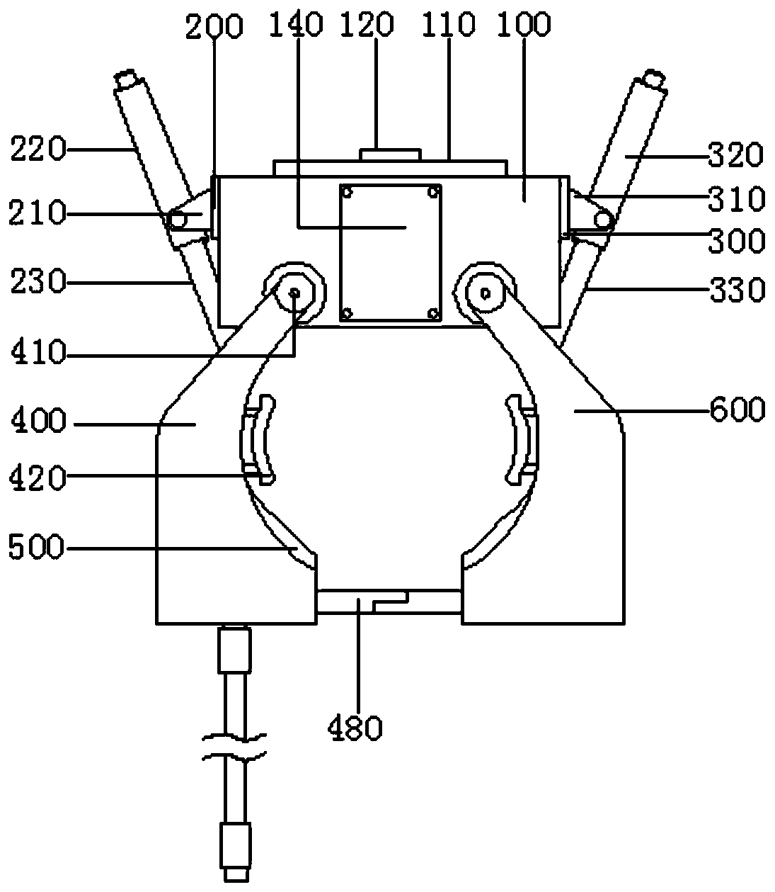
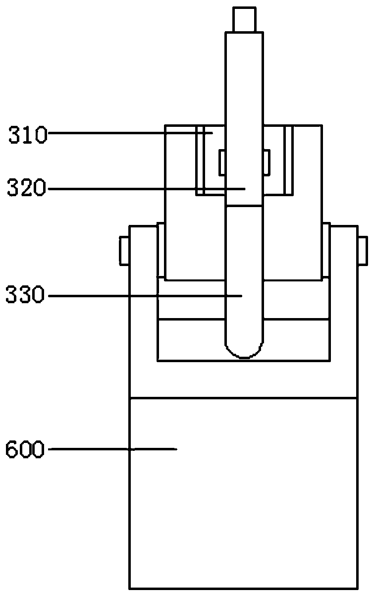
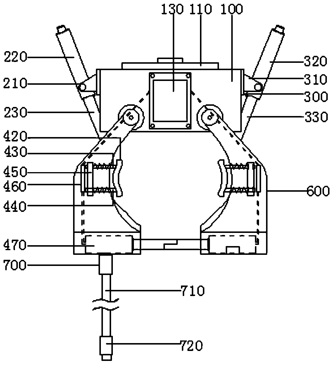
[0019] The invention provides a clamp structure for grasping mechanical equipment, which can improve the stability and safety of the clamp through the combined use of accessories, please refer to Figure 1-4 , including the top case 100, the main ear 200, the auxiliary ear 300, the main frame 400, the bearing 410, the bottom pad 500, the auxiliary frame 600 and the fixing bolt 700;

[0020] see again Figure 1-2 , the top of the top case 100 has a flip cover ...


PUM


Abstract

The invention belongs to the technical field of mechanical equipment accessories, and particularly relates to a clamp structure for grabbing mechanical equipment. The clamp structure for the grabbingmechanical equipment comprises a top shell, a main lug, an auxiliary lug, a main frame, bearings, bottom pads, an auxiliary frame and a fixed bolt; and the left side wall and the right side wall of the top shell are fixedly connected with the main lug and the auxiliary lug through screws. The clamp structure for the grabbing mechanical equipment can control a main push rod device and an auxiliarypush rod device to push a telescopic rod, after the telescopic rod influences the main frame and the auxiliary frame, logs of same specification can be clamped, after being matched with the bottom pads, the contact area is large, the friction effect is strong, the sliding probability is reduced, after being clamped, the circumferential outer walls of the logs of the same specification are contacted with side pads, the side pads are stressed to be matched with springs to retract, cross rods synchronously move to trigger trigger switches on contact plates, so that miniature electric push rods push connecting rods, the bottom protection effect is achieved, the falling prevention performance is good, the double-safety effect can be achieved, the transfer of the logs of the same specification has safety and stability, and the transfer efficiency of the logs of the same specification is improved.

Description

technical field [0001] The invention relates to the technical field of mechanical equipment accessories, in particular to a clamp structure for grabbing mechanical equipment. Background technique [0002] There are many kinds of mechanical equipment. When the mechanical equipment is running, some of its parts and even itself can perform different forms of mechanical movement. Mechanical equipment consists of driving device, transmission device, transmission device, working device, braking device, protection device, lubrication system, cooling system and other parts. [0003] The grasping mechanical equipment is a classification of mechanical equipment. The grasping mechanical equipment is mostly used for the purpose of grasping and transferring. In the grasping mechanical equipment, the clamp is an accessory that cooperates with it to complete the grasping action of the item, and is a guarantee An important part of the grabbing machinery and equipment to effectively grab it...

Claims


Application Information

Patent Timeline
Patent Type & Authority Applications(China)
IPC IPC(8): B25J15/00B65G47/90
CPCB25J15/00B65G47/90B25J15/0038
Inventor 彭林李超刘平
Owner CHANGSHA CITY WANZHENG LORRY CARRIAGE
Why Eureka
Try Eureka