Workpiece feeding, arranging and direction arranging device and technology

A technology for workpiece entry and workpiece entry. It is applied to conveyor objects, transportation and packaging, conveyors, etc., which can solve the problems of workpiece bumping, high cost, disorder and disorder, and achieve the effect of reducing collision and improving yield.

Pending Publication Date: 2019-12-10
SHENZHEN FUYUNDI TECH
View PDF0 Cites 6 Cited by
  • Summary
  • Abstract
  • Description
  • Claims
  • Application Information

AI Technical Summary

Problems solved by technology

[0002] A large number of small workpieces (or products) that are disorderly, similar or identical in shape are low in efficiency and high in cost by traditional manual nesting, which is a major problem in industrial automation production technology. Therefore, the use of automatic workpiece loading and arranging devices has been widely used application
Usually, the vibrating plate for feeding and discharging is used, but it has great limitations: the workpiece cannot be transported out in time through the primary or secondary vibration of the vibrating plate, but it is easy to cause some workpieces left in the vibrating plate to be vibrated repeatedly, resulting in The workpiece is easily damaged by bumping and friction, which increases the rate of defective quality
Especially for some workpieces that require high safety performance, the arrangement of vibrating disks can no longer meet the high application requirements for the automatic loading and arrangement method or device of the workpiece. Therefore, a more optimized automatic workpiece arrangement method or device is needed

Method used


Image

  • Workpiece feeding, arranging and direction arranging device and technology
  • Workpiece feeding, arranging and direction arranging device and technology
  • Workpiece feeding, arranging and direction arranging device and technology

Examples


Embodiment Construction

[0047] In order to make the purpose, technical solutions and advantages of the present invention more clear, the present invention will be further described in detail below in conjunction with the accompanying drawings and implementation examples. It should be understood that the specific embodiments described here are only used to explain the present invention, not to limit the present invention.

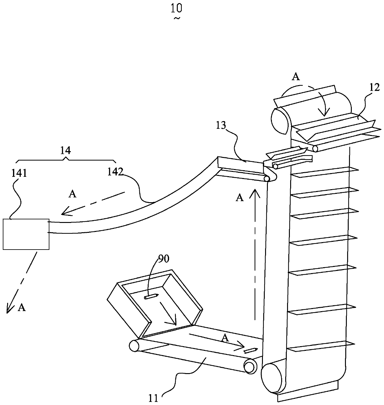
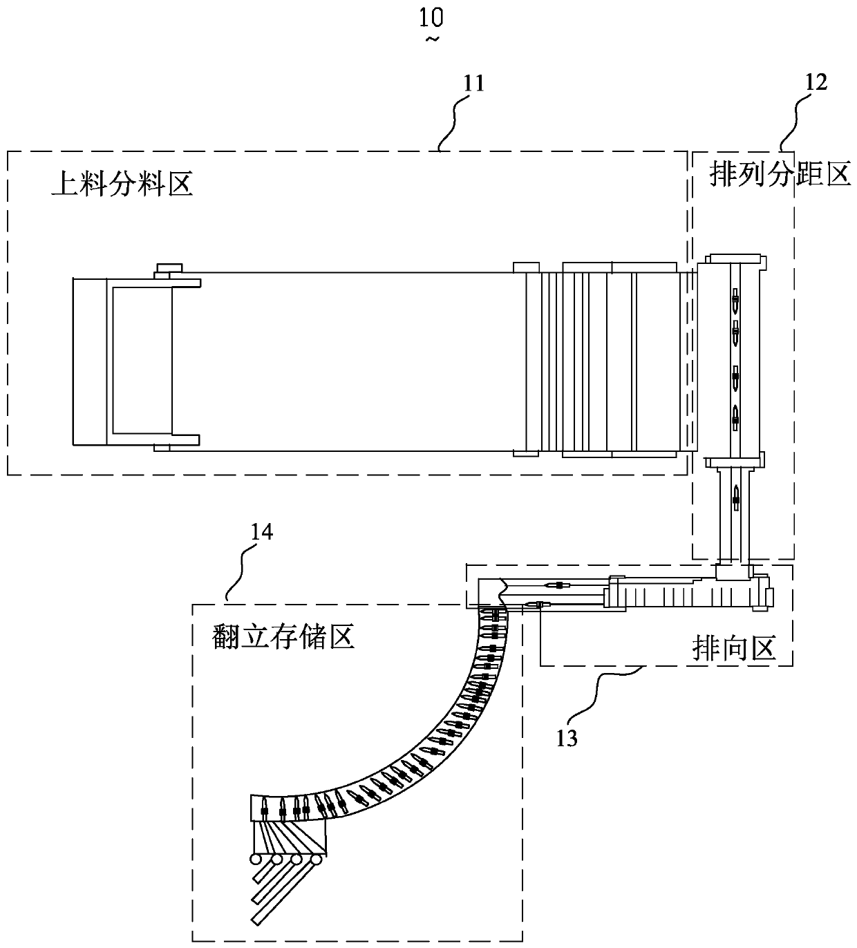
[0048] see figure 1 and figure 2 , the first embodiment of the present invention provides a workpiece loading and arranging device 10, which is used to sort the workpieces to be sorted, specifically, the workpiece feeding and arranging device 10 includes multiple After the workpiece 90 to be sorted is lifted to a preset height, based on the lowering of the multiple stations set up layer by layer, the workpiece 90 to be sorted is sequentially passed through a plurality of said workstations for corresponding arrangement and direction according to its own gravity. operate. It shou...


PUM


Abstract

The invention provides a workpiece feeding, arranging and direction arranging device and technology for sorting to-be-tidied workpieces. According to the workpiece feeding, arranging and direction arranging device, based on a plurality of stations lowered layer by layer, the gravity action of the to-be-tidied workpieces is utilized, and the multiple stations are sequentially used for conducting corresponding arranging and direction arranging operation. By adoption of the provided workpiece feeding, arranging and direction arranging device and technology, threats to operator safety during existing manual arranging can be avoided, and the problems that a vibration disc is adopted for repeated vibration and friction, product surface scratches are caused, and the quality is not good can be solved. According to the provided workpiece feeding, arranging and direction arranging device and technology, the gravity action of the to-be-tidied workpieces is utilized, the correspondingly-matched stations are matched, accordingly, the arranging and direction arranging operation on the to-be-tidied workpieces is achieved, and the cost of an integral arranging and direction arranging structure canbe lower.

Description

【Technical field】 [0001] The invention relates to the technical field of workpiece automatic loading and arranging devices, in particular to a workpiece feeding and arranging device and its technology. 【Background technique】 [0002] A large number of small workpieces (or products) that are disorderly, similar or identical in shape are low in efficiency and high in cost by traditional manual nesting, which is a major problem in industrial automation production technology, so the use of automatic workpiece loading and arranging devices has been widely used application. Usually, the vibrating plate for feeding and discharging is used, but it has great limitations: the workpiece cannot be transported out in time through the primary or secondary vibration of the vibrating plate, but it is easy to cause some workpieces left in the vibrating plate to be vibrated repeatedly, resulting in The workpiece is easily damaged by bumping and friction, which increases the rate of defective...

Claims


Application Information

Patent Timeline
Patent Type & Authority Applications(China)
IPC IPC(8): B65G47/248B65G47/252B65G47/31
CPCB65G47/248B65G47/252B65G47/31B65G2203/041
Inventor 彭友品
Owner SHENZHEN FUYUNDI TECH
Why Eureka
Try Eureka