Wireless tag writing device and method, readable storage medium and electronic device

A wireless tag, wireless technology, applied in printing devices, collaborative devices, memory record carrier reading problems, etc., can solve problems such as time required

Pending Publication Date: 2019-12-10
TOSHIBA TEC KK
View PDF5 Cites 3 Cited by
  • Summary
  • Abstract
  • Description
  • Claims
  • Application Information

AI Technical Summary

Problems solved by technology

Therefore, when a plurality of RFID tags are formed at wide intervals on th

Method used


Image

  • Wireless tag writing device and method, readable storage medium and electronic device
  • Wireless tag writing device and method, readable storage medium and electronic device
  • Wireless tag writing device and method, readable storage medium and electronic device

Examples


no. 1 example

[0059] Hereinafter, a first embodiment of the wireless tag writing device will be described in detail with reference to the drawings. In addition, the first embodiment described below is an example in which the wireless tag writing device of the present invention is applied to an RFID printing device.

[0060] Explanation of the schematic configuration of the printing device

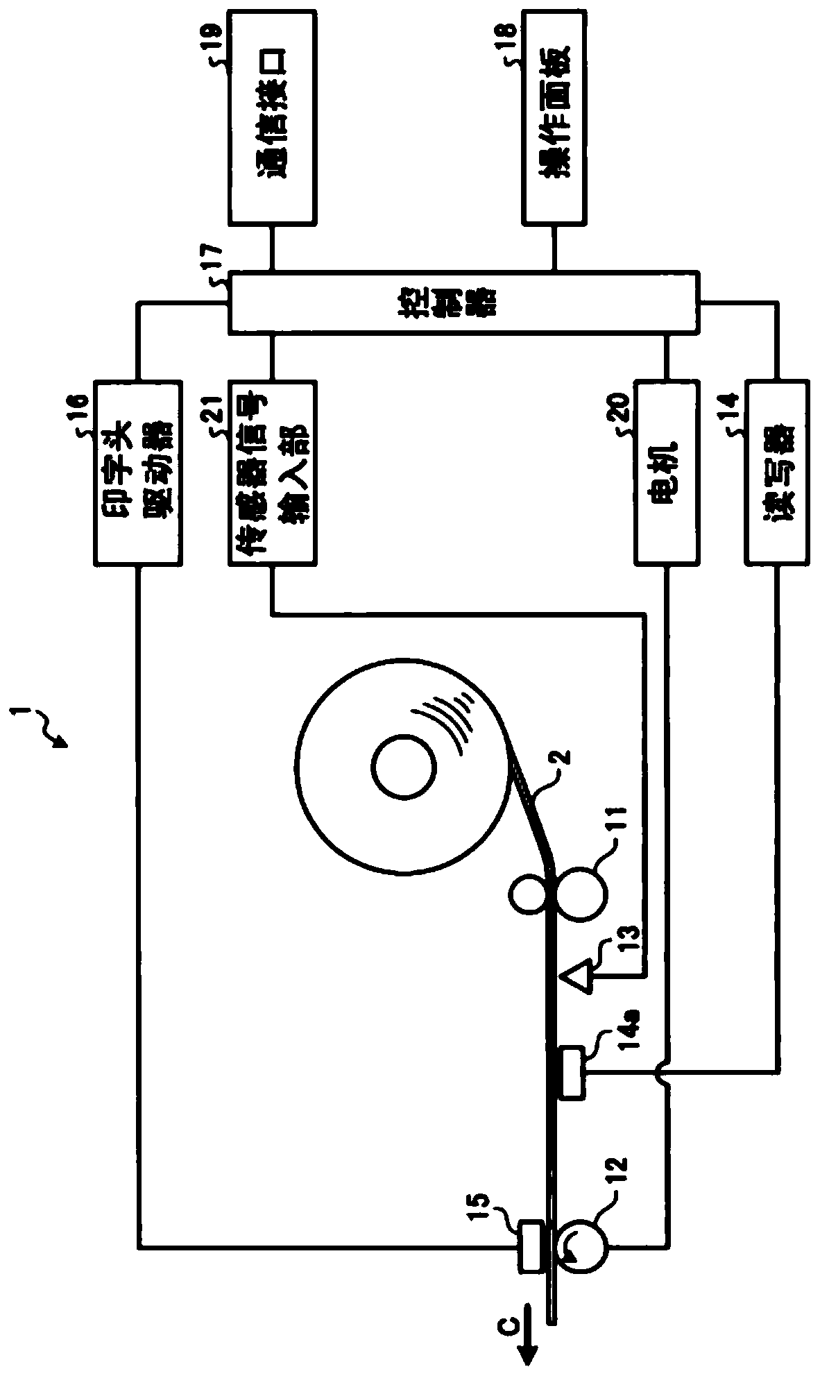
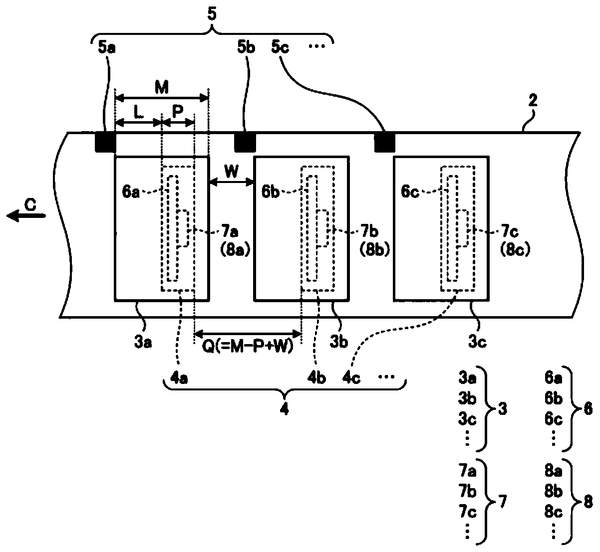
[0061] figure 1 It is a configuration diagram showing a schematic configuration of the RFID printing apparatus 1 according to the first embodiment. The RFID printing device 1 conveys a label (label, label) backing paper 2 formed in a roll shape, and prints a plurality of label papers 3 (3a, 3b, 3c, . . . ...) (cf. figure 2 ) to print on. In addition, the RFID printing apparatus 1 transfers the label backing paper 2 while printing the RFID tags 4 (4a) formed on each of the label sheets 3 (3a, 3b, 3c, . . . ). , 4b, 4c, ...) (refer to figure 2 ) to write information. In addition, the RFID printing...

no. 2 example

[0126] Hereinafter, a second embodiment of the wireless tag writing device will be described in detail with reference to the drawings. The second embodiment described below is an example in which the wireless tag writing device of the present invention is applied to the RFID printing device 1a. In particular, the RFID printing apparatus 1a shown in the second embodiment has a layout in which the label paper 3 and the RFID label 4 pasted on the label backing paper 2 are measured before calibration, and based on the measurement results, it is set to transport the label when calibration is performed. The function of the conveying pitch p of the sign backing paper 2.

[0127] The RFID printing device 1 a has substantially the same hardware configuration as the RFID printing device 1 . Therefore, among the constituent elements and functional elements of the RFID printing apparatus 1a, the same elements as those of the RFID printing apparatus 1 will be described using the same symb...


PUM


Abstract

The present invention discloses a wireless tag writing device and method, a readable storage medium, and an electronic device, which can perform correction work in a short time regardless of the setting interval of an RFID tag in which information is written, the wireless tag writing device comprising a setting unit, a correction unit, and a writing unit. A correction execution unit, which is a correction unit, uses a conveyance pitch setting unit, which is a setting unit, to convey label paper on the basis of a conveyance pitch set on the basis of information including the arrangement state of a plurality of pieces of label paper adhered to the label paper. And specifies a position at which information is written to an RFID tag that is a wireless tag, a wireless output value at the time of writing information, and a threshold value for determining, for the wireless output value, a response signal from the RFID tag to be written and a response signal from an RFID tag that is not to bewritten. An information writing unit, which is a writing unit, writes information to the wireless output value specified by the correction execution unit for the writing position specified by the correction execution unit.

Description

[0001] This application claims that the Japanese application with the filing date of June 1, 2018 and the application number of JP2018-105937 is the priority, and cites the content of the above-mentioned application, and the entire disclosure content is hereby incorporated by reference. technical field [0002] Embodiments of the present invention relate to a wireless tag writing device, a wireless tag writing method, a non-transitory computer-readable storage medium, and electronic equipment. Background technique [0003] Currently, when the conditions for writing RFID tags are determined by a tag (label) printer compatible with RFID (Radio Frequency IDentification: radio frequency identification), the information is executed while the RFID tags actually used are transported at a certain distance. Write and read, and determine the correct write position for correction operations. [0004] Specifically, the calibration work is performed by always moving the tag backing paper...

Claims


Application Information

Patent Timeline
IPC IPC(8): G06K17/00B41J29/38
CPCG06K17/00B41J29/38G06K1/20G06K7/0008G06K19/0723G06K19/07796G06K17/0025G06K19/07718
Inventor 土本宏志
Owner TOSHIBA TEC KK
Why Eureka
Try Eureka