Wall switch socket front side wiring system
A wiring system and wall switch technology, applied in the direction of electric switches, connections, contact parts, etc., can solve problems such as poor contact, achieve stable and reliable contact, increase safety, and reduce the difficulty of installation and operation
- Summary
- Abstract
- Description
- Claims
- Application Information
AI Technical Summary
Problems solved by technology
Method used
Image

Examples
Embodiment 1
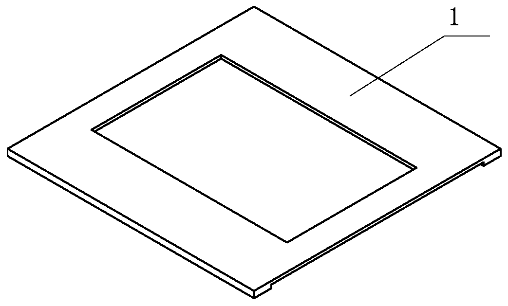
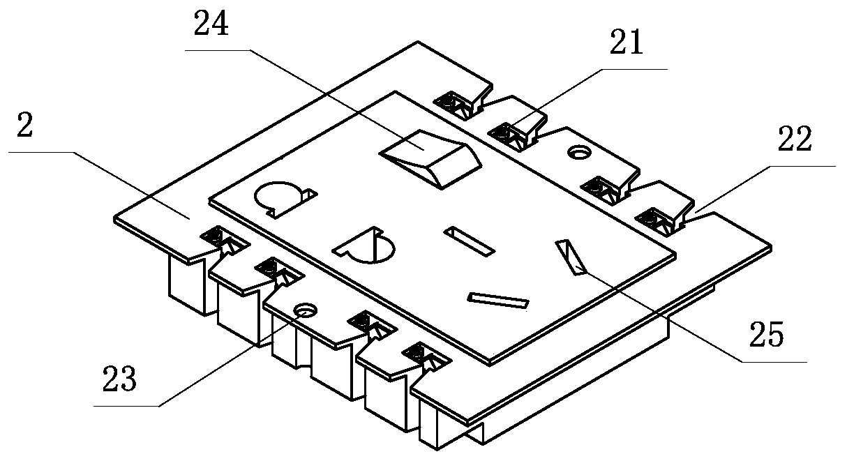
[0039] Embodiment 1: Installation of Panel A2
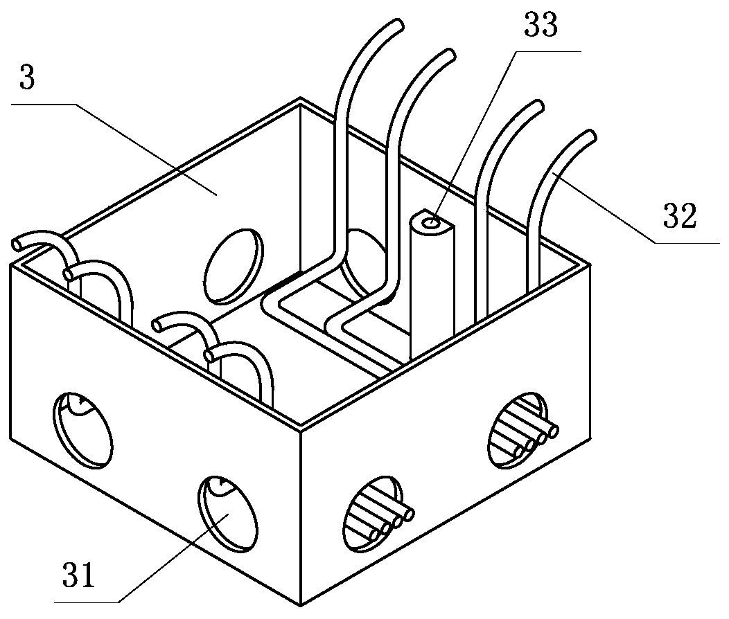
[0040] During installation, the wall bottom box 3 has been fixed on the wall where the switch socket needs to be installed according to the standard requirements. The follow-up installation process is briefly described as follows: Step 1, the wire 32 enters the wall bottom box 3 through the wire inlet and outlet hole 31, and goes along the panel A2. The position of the leading wire opening 22 protrudes from the wall surface, leaving sufficient wiring length; in the second step, pre-place the panel A2 on the bottom box 3, arrange the reserved wires 32 in the first step to the corresponding leading wire opening 22, and install the screws through Through the fixing hole 23 and the fixing seat 33, securely install and fix the panel A2 on the bottom box 3; step 3, remove the insulation of the clamping part of the wire 32 and the terminal block A21, and press the terminal block A21 from the lead port 22 Clamping part; step 4, tighten t...
Embodiment 2
[0042] Embodiment 2: Installation of Panel B4
[0043] During installation, the wall bottom box 3 has been fixed on the wall where the switch socket needs to be installed according to the standard requirements. The subsequent installation process is briefly described as follows: Step 1, the wire 32 enters the wall bottom box 3 through the wire inlet and outlet hole 31, leaving enough wiring length The second step is to install the wire management frame 5 on the bottom box 3, the installation reserved hole 52 on the wire management frame 5 corresponds to the fixing seat 33 on the bottom box 3, and the electric wire 32 is hollowed out from the middle of the wire management frame 5 Pass through; step 3, according to the position of the terminal block B42 on the panel B4, press the wire 32 into the corresponding cable management clamp 51, so that the wire 32 is perpendicular to the installation plane; step 4, face the panel B4 to the bottom box 3 , carefully insert the wire 32 cla...
Embodiment 3
[0046] Embodiment 3: Replacement between terminal blocks
[0047] After the side opening of terminal block C61 and terminal block E63, the terminal block A21 in panel A2 can be replaced; terminal block D62 can directly replace terminal block A21 in panel A2; terminal block C61 and terminal block E63 can directly replace the terminal block in panel B4 Terminal block B42.
PUM
 Abstract
Description
Claims
Application Information
 - R&D
- Intellectual Property
- Life Sciences
- Materials
- Tech Scout
- Unparalleled Data Quality
- Higher Quality Content
- 60% Fewer Hallucinations
Browse by: Latest US Patents, China's latest patents, Technical Efficacy Thesaurus, Application Domain, Technology Topic, Popular Technical Reports.
© 2025 PatSnap. All rights reserved.Legal|Privacy policy|Modern Slavery Act Transparency Statement|Sitemap|About US| Contact US: help@patsnap.com