Tubing structure

一种管件、磁性件的技术,应用在管件结构领域,能够解决固持力不足、管件结构弯折角度易受到外力而改变、管件结构无法被调整到弯折角度等问题,达到使用方便的效果

Active Publication Date: 2019-12-10
WISTRON CORP
View PDF9 Cites 0 Cited by
  • Summary
  • Abstract
  • Description
  • Claims
  • Application Information

AI Technical Summary

Problems solved by technology

However, the existing pipe structure still has some disadvantages. For example, the holding force between two adjacent single structures is insufficient, so that the bending angle of the pipe structure is easily changed by external force; There is no way to touch the pipe fitting structure due to the limitation of the pipe fitting structure. At this time, the pipe fitting structure cannot be adjusted to the required bending angle. Therefore, the existing pipe fitting structure still needs to be improved.

Method used


Image

  • Tubing structure
  • Tubing structure
  • Tubing structure

Examples


Embodiment Construction

[0061] In order to have a clearer understanding of the technical solutions, objectives and effects of the present invention, the specific implementation manners of the present invention will now be described with reference to the accompanying drawings.

[0062] The directional terms mentioned in the following embodiments, such as: up, down, left, right, front or back, etc., are only directions referring to the attached drawings. Accordingly, the directional terms are used to illustrate and not to limit the invention.

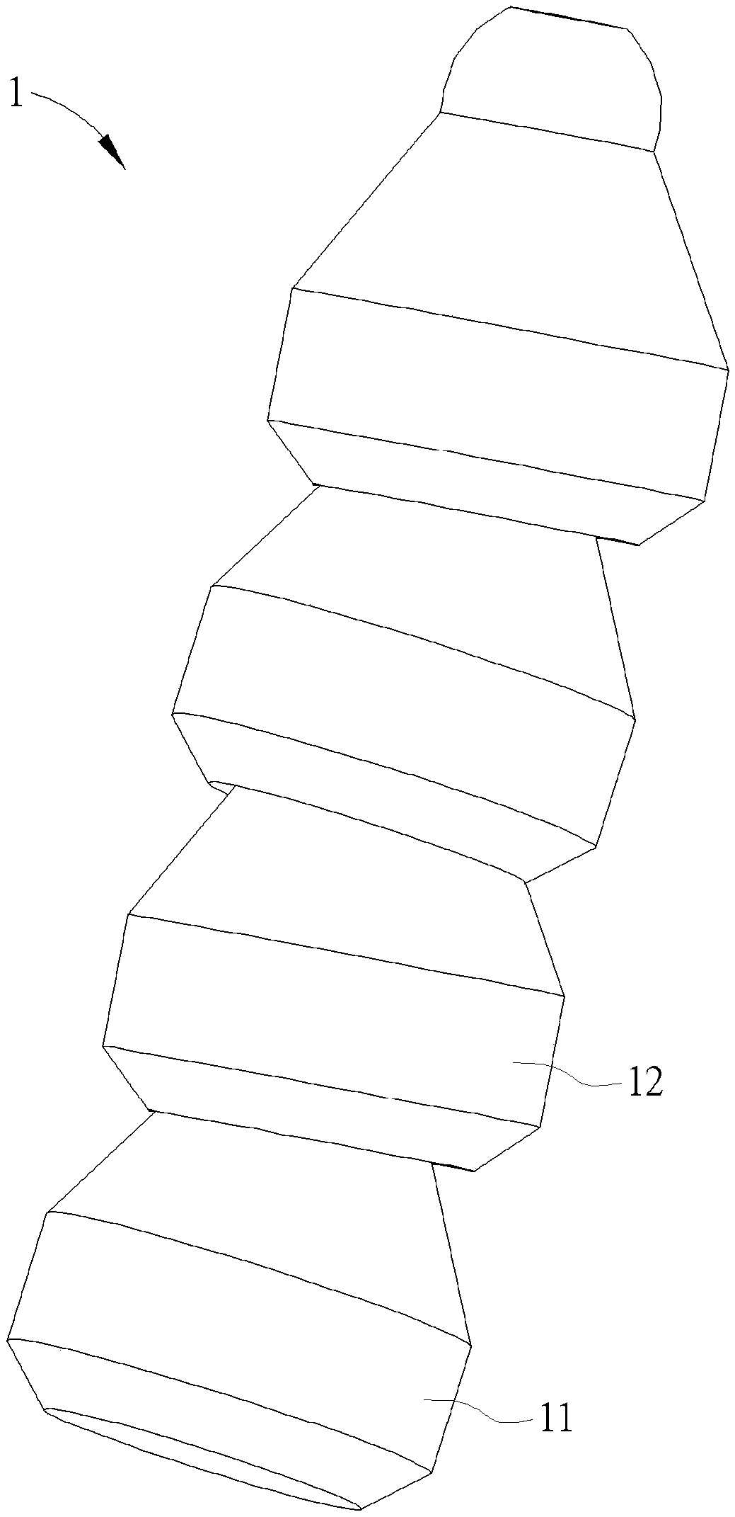
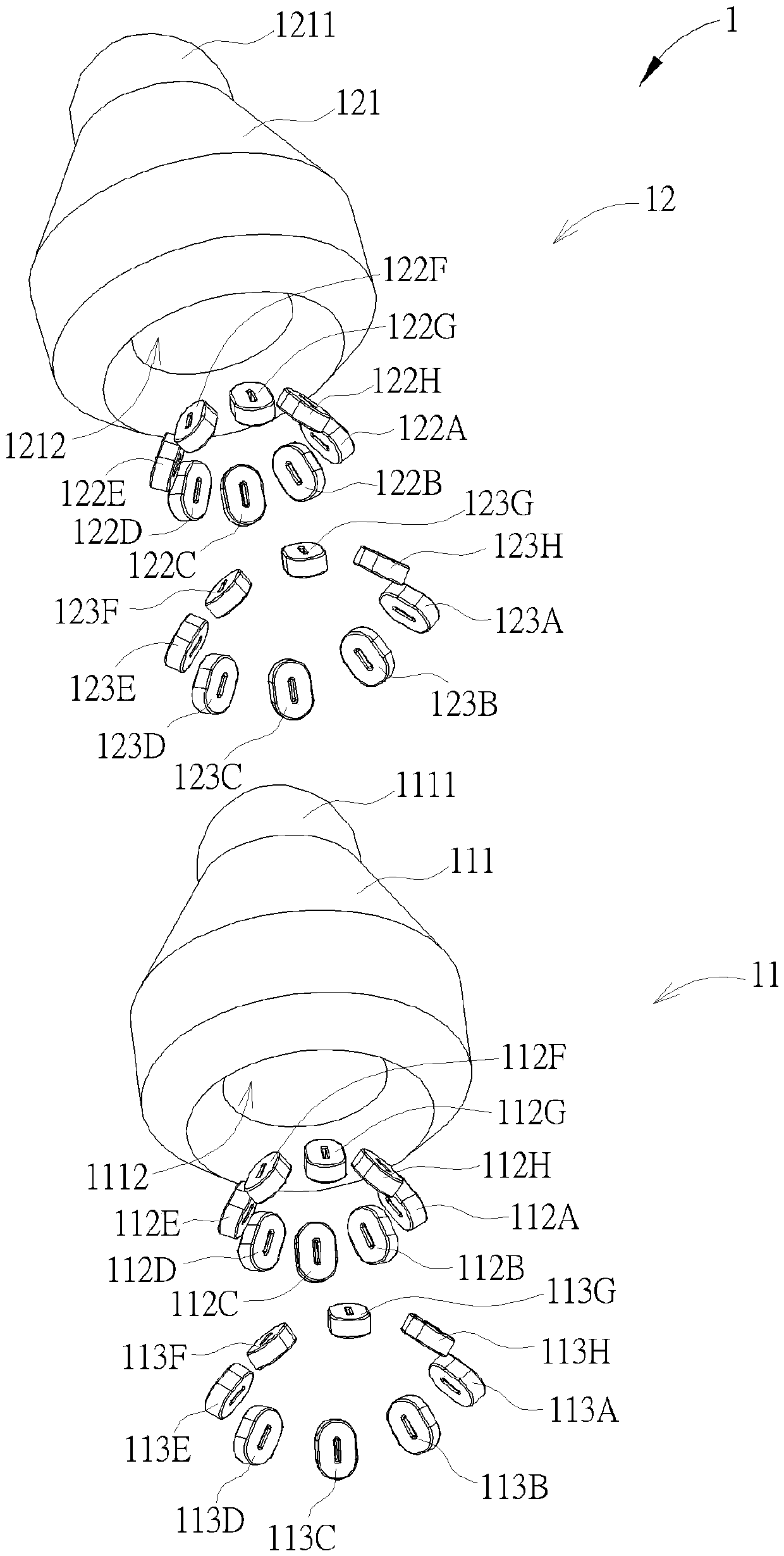
[0063] see figure 1 , figure 1 It is a schematic view of the appearance of a pipe structure 1 according to the first embodiment of the present invention. Such as figure 1 As shown, the pipe structure 1 can be composed of a plurality of units including at least a first unit 11 and a second unit 12. The number of units included in the pipe structure 1 is not limited to that shown in the accompanying drawings of the present invention. Depending on the design re...


PUM


Abstract

A tubing structure includes a first unit, a second unit movably connected to the first unit, and a controller. The first unit includes a first body and at least one first magnetic component disposed inside the first body. The second unit includes a second body movably engaging with the first body and at least one second magnetic component disposed inside the second body and located at a position corresponding to the at least one first magnetic component. The controller is electrically connected to at least one of the at least one first magnetic component and the at least one second magnetic component. The controller selectively controls the at least one first magnetic component and the at least one second magnetic component to magnetically attract or repulse each other to drive the secondbody to move relative to the first body for inclining the second unit relative to the first unit. Thereby, the purpose of adjusting the bending angle of the tubing structure is achieved.

Description

technical field [0001] The invention relates to a pipe fitting structure controlled by magnetic force, especially a pipe fitting structure using the magnetic force generated between different single structures to control the overall movement. Background technique [0002] A pipe fitting structure (such as a coiled pipe) composed of a section of a single structure is often used to cover electrical circuits to prevent electrical circuits from being bent, knotted and corroded by moisture, or as a bracket for electronic devices to allow Users can fix the electronic device at a specific angle by bending the tube structure according to their needs. However, the existing pipe structure still has some shortcomings. For example, the holding force between two adjacent single structures is insufficient, so that the bending angle of the pipe structure is easily changed by external force; There is no way to touch the pipe fitting structure due to the limitation of the pipe fitting struc...

Claims


Application Information

Patent Timeline
Patent Type & Authority Applications(China)
IPC IPC(8): H02G3/04
CPCH02G3/04F16L11/18H01F7/064F16L27/04H01F7/0205H02G3/0475
Inventor 曾天仲
Owner WISTRON CORP
Why Eureka
Try Eureka