
OPF optimization and reactive compensation distribution method for power system

An optimization method and power system technology, applied in the direction of reactive power compensation, reactive power adjustment/elimination/compensation, electrical components, etc., can solve the problem of insufficient reactive power compensation, discontinuity of reactive power injection, and failure to find the power system Optimum allocation method and other issues to achieve good optimization results, simplify the search space and the effect of computing costs

Active Publication Date: 2019-12-10
SHENZHEN INST OF RES & INNOVATION THE UNIV OF HONG KONG
View PDF1 Cites 0 Cited by
  • Summary
  • Abstract
  • Description
  • Claims
  • Application Information

AI Technical Summary

Problems solved by technology

Due to the continuous increase of load, the network structure and power distribution of the power system need to be constantly changed. If the reactive power compensation of the power system is unreasonable, it will cause insufficient reactive power compensation in some areas, and even lead to the stability of the power system. serious sexual problems
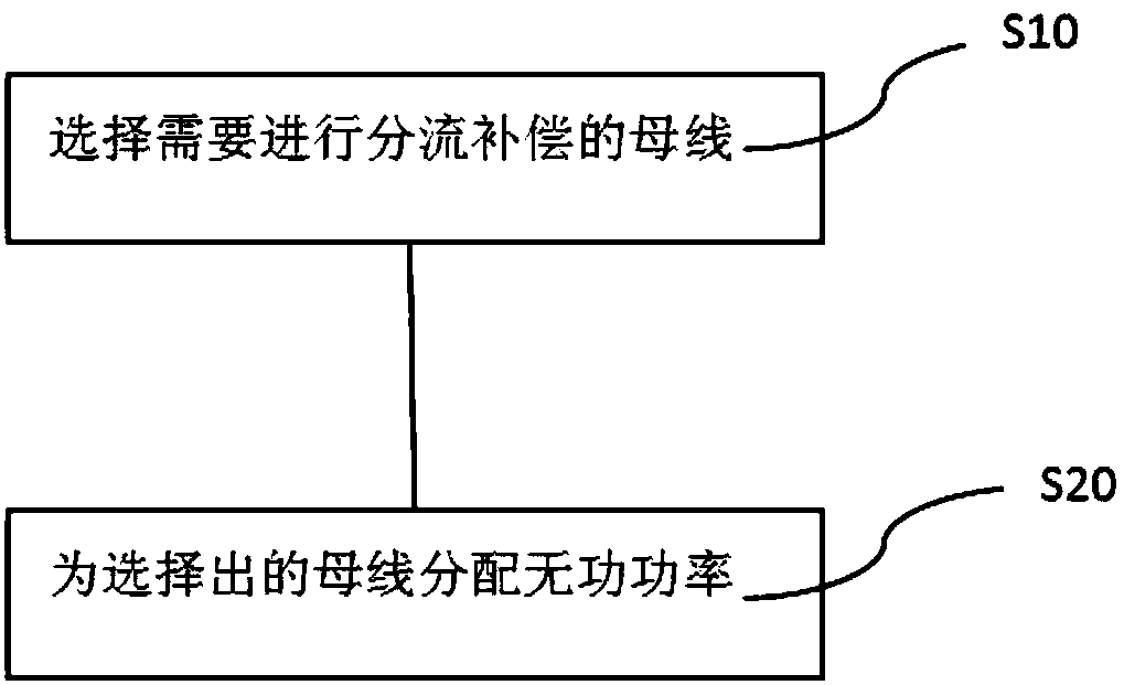
[0003] In order to ensure the stable operation of the power system and reduce the operating cost at the same time, Optimal Power Flow (OPF) is often used for optimization in modern power grids. Due to the discontinuity of reactive power injection in the power system, the OPF problem will include Constraints of discrete variables. In the prior art, a series of algorithms are usually used to calculate the above discrete variables, for example, linear / nonlinear programming algorithm or interior point method, etc., but the computational complexity of these algorithms will increase with the scale of the system. Gradually increase and continue to increase, and even the optimal solution cannot be obtained or the convergence does not occur, which makes it impossible to find the optimal distribution method suitable for the power system when performing reactive power compensation

Method used


Image

  • OPF optimization and reactive compensation distribution method for power system
  • OPF optimization and reactive compensation distribution method for power system
  • OPF optimization and reactive compensation distribution method for power system

Examples


Embodiment Construction

[0040] In order to make the object, technical solution and advantages of the present invention clearer, the present invention will be further described in detail below through specific embodiments in conjunction with the accompanying drawings. It should be understood that the specific embodiments described here are only used to explain the present invention, not to limit the present invention.

[0041] OPF is a typical nonlinear programming problem, and its mathematical model mainly includes objective function and constraint conditions. For the OPF optimization of the power system, when the disturbance variables in the system (such as load conditions) are constant, the control variables (such as active power, reactive power or node voltage, etc.) and state variables (such as node voltage) can be adjusted within a certain range. Voltage amplitude or intersection, etc.), so as to obtain the best power flow distribution that can be used to optimize the power system. Commonly use...


PUM


Abstract

The invention relates to an OPF optimization method for a power system. The method comprises steps that discretely distributed control variables in a line connected with any bus are added into constraint conditions of an OPF model, and reactive power constraint conditions associated with any bus and provided with the discretely distributed control variables are obtained; according to the reactivepower constraint conditions with the discretely distributed control variables, an upper limit value of the reactive power which can be generated by any bus is reset; a control variable OPF-SHC model with the discrete distribution is established by utilizing the upper limit value, and the control variable OPF-SHC model is applied to power system optimization.

Description

technical field [0001] The invention relates to the technical field of power systems, in particular to an OPF optimization and reactive power compensation distribution method for power systems. Background technique [0002] In today's world, the rapid development of economy and the rapid progress of science and technology have led to the improvement of people's living standards, and subsequently, people's demand for electric energy has also increased significantly, which puts forward the reliability and quality of power supply system. higher requirement. Due to the continuous increase of load, the network structure and power distribution of the power system need to be constantly changed. If the reactive power compensation of the power system is unreasonable, it will cause insufficient reactive power compensation in some areas, and even lead to the stability of the power system. serious sexual problems. [0003] In order to ensure the stable operation of the power system an...

Claims


Application Information

Patent Timeline
IPC IPC(8): H02J3/06H02J3/18
CPCH02J3/06H02J3/1871Y02E40/30
Inventor R·哈桑尼艾特马侯云鹤李安国
Owner SHENZHEN INST OF RES & INNOVATION THE UNIV OF HONG KONG
Learn More