
Unpowered constant speed drainage flow control device

A power and water outlet control technology, applied in water supply devices, sewage discharge, waterway systems, etc., can solve the cost of flow control devices, difficulties in transportation, installation, maintenance, difficulty in providing power sources and electromechanical equipment, and increase the size of flow control devices and quality issues, to achieve the effect of simple and convenient project implementation, operation and maintenance, accurate planning of water adjustment and storage, and reduction of runoff peak flow

Pending Publication Date: 2019-12-13
上海同晟环保科技有限公司
View PDF0 Cites 0 Cited by
  • Summary
  • Abstract
  • Description
  • Claims
  • Application Information

AI Technical Summary

Problems solved by technology

The discharge method using gravity does not require external power supply, but as the water level in the storage space of the water body decreases, the discharge flow will continue to decrease, and the effluent flow will vary greatly, which requires a long period to achieve slow and uniform water flow. In the release environment, this method is not applicable
Using water pumps or other power devices combined with water level control facilities, the water volume in the storage space can be discharged in a planned and controlled manner with a stable flow rate, but in many environments, it is difficult to provide a stable power source and electromechanical equipment; even if there is a power source, it will be due to engineering Implementation, operation and maintenance are complicated, and it is difficult to apply and promote
[0005] The flow control devices used in artesian systems in the prior art often include drain pipes and floats (such as float valves) to eliminate water pressure differences. During the flow control process, the buoyancy provided by the floats is required to overcome the gravity of the floats themselves and the external water pressure. In order to hold up the float, in order to obtain greater buoyancy, the size of the float needs to be designed to be large, which will increase the size and quality of the entire flow control device, thereby bringing costs, transportation, installation, and maintenance to the flow control device. difficulty

Method used


Image

  • Unpowered constant speed drainage flow control device
  • Unpowered constant speed drainage flow control device
  • Unpowered constant speed drainage flow control device

Examples


Embodiment Construction

[0032] The present invention will now be described in further detail with reference to the accompanying drawings. These drawings are all simplified schematic diagrams, and only illustrate the basic structure of the present invention in a schematic manner, so they only show the structures related to the present invention.

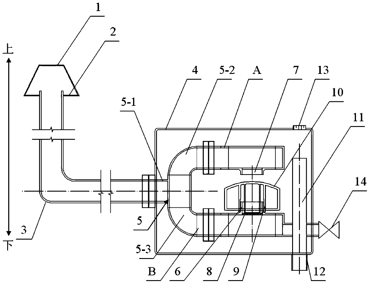
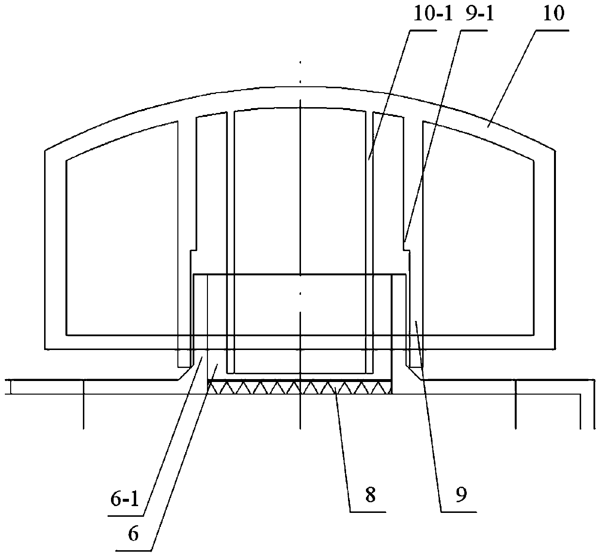
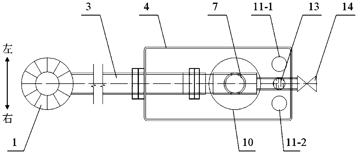
[0033] like Figure 1-3 As shown in the figure, an unpowered uniform drainage flow control device includes a water inlet head 1, a water inlet filter screen 2, a water inlet pipe 3, a box body 4, a shunt tee 5, an upper pipe body A, a lower pipe body B, and a lower pipe body. Hydraulic communication port 6, upper inflow port 7, lower protective filter screen 8, socket sliding part 9, floating water stop part 10, water outlet control pipe 11, water outlet 12, vent cap 13, drain valve 14; among them,

[0034] The water inlet head 1 is arranged at one end of the water inlet pipe 3 and communicates with the interior of the water inlet pipe 3. The water inlet he...


PUM


Abstract

The invention relates to an unpowered constant speed drainage flow control device. The unpowered constant speed drainage flow control device is characterized by comprising a water inlet head (1), a water inlet filter screen (2), a water inlet pipe (3), a box body (4), a flow-dividing tee-junction (5), an upper part pipe body (A), a lower part pipe body (B), a lower part water pressure communication opening (6), an upper part inflow opening (7), a lower part protective filter screen (8), a socket sliding part (9), a floating water-stop part (10), a water outlet control pipe (11), a water outlet(12), a vent cap (13) and a blow-down valve (14); and buoyancy force of the floating water-stop part and water pressure difference are used for overcoming a function of own gravity to meet the requirement of slowly and uniformly releasing water volume in a longer period, power is not required to be provided externally, the unpowered constant speed drainage flow control device is suitable for places where power sources are difficult to supply, and the unpowered constant speed drainage flow control device has wide applicability.

Description

technical field [0001] The invention relates to the technical field of water purification and control, in particular to an unpowered constant-speed drainage flow control device. Background technique [0002] Building a sponge city means that the city can absorb, store, seep and purify water like a sponge when it rains, and “release” and use the stored water when needed. One of the important control objectives involved in the Technical Guidelines for Sponge City Construction - "control" in the term "total control of rainwater runoff" refers to total control, that is, including the total amount of runoff pollutants and the volume of runoff. [0003] In the sponge city construction (new construction, renovation) project, it actually meets the requirements of sponge city construction, and can design and calculate the effective storage capacity of sponge facilities: it means that the facility can store the quantitative rainwater in the facility when it rains. After a period of t...

Claims


Application Information

Patent Timeline
Patent Type & Authority Applications(China)
IPC IPC(8): E03F1/00E03F3/02
CPCE03F1/003E03F1/005E03F3/02
Inventor 易威王坚伟穆毅陈繁
Owner 上海同晟环保科技有限公司
Learn More