Casing installation device for casing drilling rig

A technology for installing equipment and casing, applied in drilling equipment, casing, drill pipe and other directions, can solve the problems of annular drill bit damage, consumption of drilling rig impact power, high manual work intensity, etc., to achieve the effect of avoiding deformation

Pending Publication Date: 2019-12-13
ZHEJIANG MOBILE HYDRAULIC POWER TECH
View PDF0 Cites 1 Cited by
  • Summary
  • Abstract
  • Description
  • Claims
  • Application Information

AI Technical Summary

Problems solved by technology

[0003] At present, due to the lack of suitable equipment, the connecting casing relies on manual use of two casing wrenches or chain wrenches to cooperate with each other to rotate the casing, and thread the two casings together.
This method has low efficiency, high manual work intensity, and high operation risk factor; in order to ensure the concentricity of the casing and the drill pipe, it is necessary to add a brazing device in the middle of the drill arm to realize the centering of the casing; The dual tasks of drilling and dragging the casing, the dragging resistance of the casing also consumes the impact power of the drilling rig to a certain extent, affects the drilling efficiency of the drilling rig, and causes premature damage to the annular drill bit, and the drilling operation is terminated early. The maximum drilling depth of the drilling rig is shortened, which seriously limits the effective use of the drilling rig's superior drilling performance

Method used


Image

  • Casing installation device for casing drilling rig

Examples


Embodiment Construction

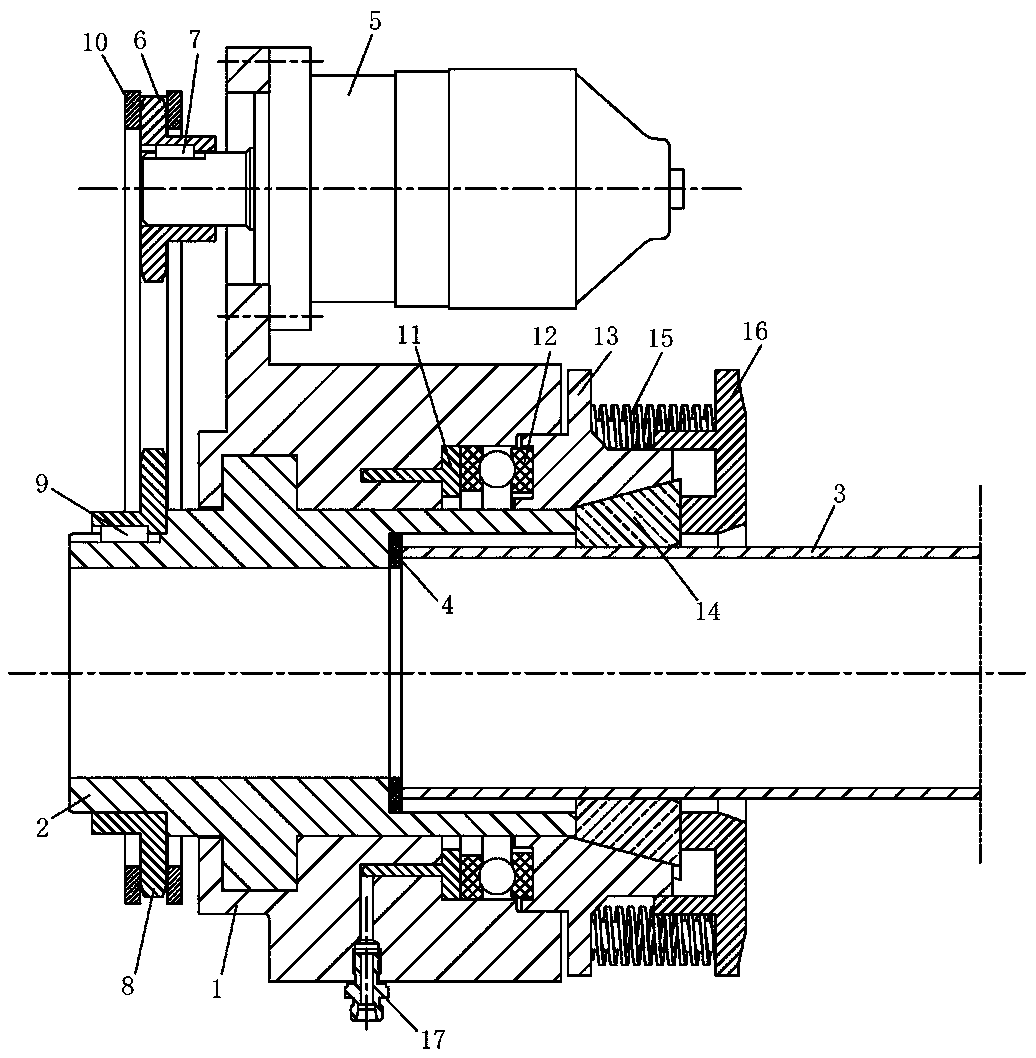
[0013] Embodiments of the present invention will be described in further detail below in conjunction with the accompanying drawings.

[0014] Such as figure 1 As shown, a casing installation device for a follow-through drilling rig includes a support frame 1, a central shaft 2, and a casing 3. The central shaft 2 is arranged in the inner cavity of the support frame 1, and the central shaft 2 can perform rotary motion relative to the support frame 1. ; The sleeve 3 is located in the inner cavity of the central shaft 2, and the connection between the central shaft 2 and the sleeve 3 is provided with a washer 4, and the washer 4 is made of rubber material and has certain elasticity.

[0015] One side of the support frame 1 is provided with a motor 5, and the motor 5 bearing is provided with a sprocket I6, and the sprocket I6 and the motor 5 bearing rotate synchronously through the key I7; one end of the central shaft 2 is provided with a sprocket II8, and the sprocket II8 It rot...


PUM


Abstract

The invention provides a casing installation device for a casing drilling rig. The casing installation device for the casing drilling rig comprises a supporting frame, a center shaft and a casing, thecenter shaft is arranged in an inner cavity of the supporting frame, and the casing is arranged in an inner cavity of the center shaft. A motor is arranged on one side of the supporting frame, a chain wheel I is arranged on a bearing of the motor, and the chain wheel I and the bearing of the motor rotate synchronously by a key I; a chain wheel II is arranged at one end of the center shaft, the chain wheel II and the center shaft synchronously rotate by a key II, and the chain wheel I is connected with the chain wheel II through a chain to transmit rotation torque; and annular oil cylinders inthe supporting frame are connected with joints on the outer side of the supporting frame through pipelines, the annular oil cylinders, bearings and compression rings are sequentially connected to oneanother in a fit mode, 3-6 springs are arranged on the outer side of each compression ring, 3-6 clamp blocks are arranged on an inclined groove in the inner side of each compression ring, and an endcover is fixed to the center shaft and connected with the springs and clamp blocks separately in a fit mode. The casing installation device for the casing drilling rig has the advantages of realizinga centering function of the casing and being capable of clamping the casing, rotating the casing and automatically tightening the casing, abutting against the casing to move forward and avoiding deformation of the tail part of the casing.

Description

technical field [0001] The invention relates to the technical field of pipe-following drilling rigs, in particular to casing installation equipment for pipe-following drilling rigs. Background technique [0002] The casing construction of the tubular drilling rig usually needs to connect and install the casing, and straighten the casing to ensure that it is basically concentric with the drill pipe. During the drilling process, the casing follows the drill bit into the hole under the tension of the annular drill bit at the front end. [0003] At present, because there is no suitable equipment, the connecting casing relies on manual use of two casing pliers or chain wrenches to cooperate with each other to rotate the casing, and the two casings are threaded together. This method has low efficiency, high manual work intensity, and high operation risk factor; in order to ensure that the casing and the drill pipe are concentric, it is necessary to add a brazing device in the midd...

Claims


Application Information

Patent Timeline
Patent Type & Authority Applications(China)
IPC IPC(8): E21B17/10E21B19/10E21B19/18
CPCE21B17/1078E21B19/10E21B19/18
Inventor 王兆民于会友沈国泉姜海明
Owner ZHEJIANG MOBILE HYDRAULIC POWER TECH
Why Eureka
Try Eureka