
Self-expanding automatic oil drain device

A technology of automatic venting and self-expansion, applied in wellbore/well valve devices, drilling equipment, wellbore/well components, etc., to avoid mechanical failures, improve operating efficiency, and simplify operating procedures

Inactive Publication Date: 2019-06-07
大庆吉庆雨科技开发有限公司
View PDF0 Cites 10 Cited by
  • Summary
  • Abstract
  • Description
  • Claims
  • Application Information

AI Technical Summary

Problems solved by technology

[0003] In order to solve the problems in the background technology, the present invention provides a self-expanding automatic oil draining device. The oil draining process of the present invention does not require pressurization, throwing heavy objects, repeated lifting and releasing, eliminating tedious procedures, and greatly The operation efficiency is greatly improved, and at the same time, it has the backwashing function to meet the needs of oilfield backwashing operations and fluid measurement

Method used

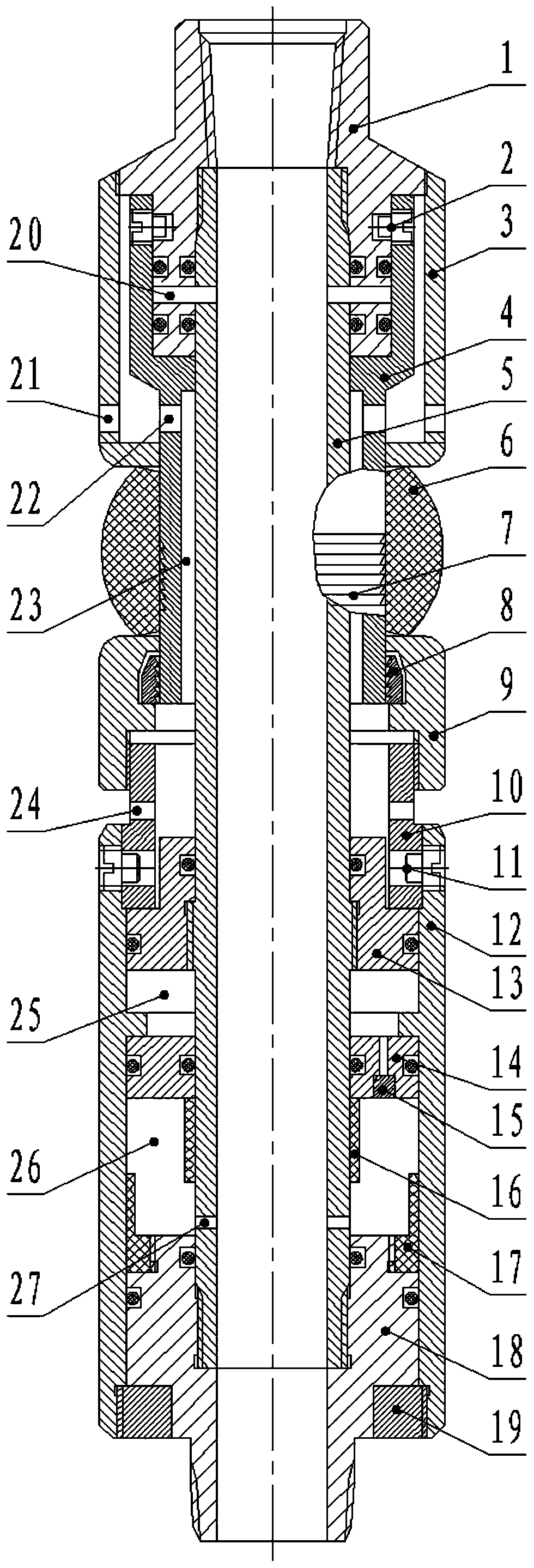
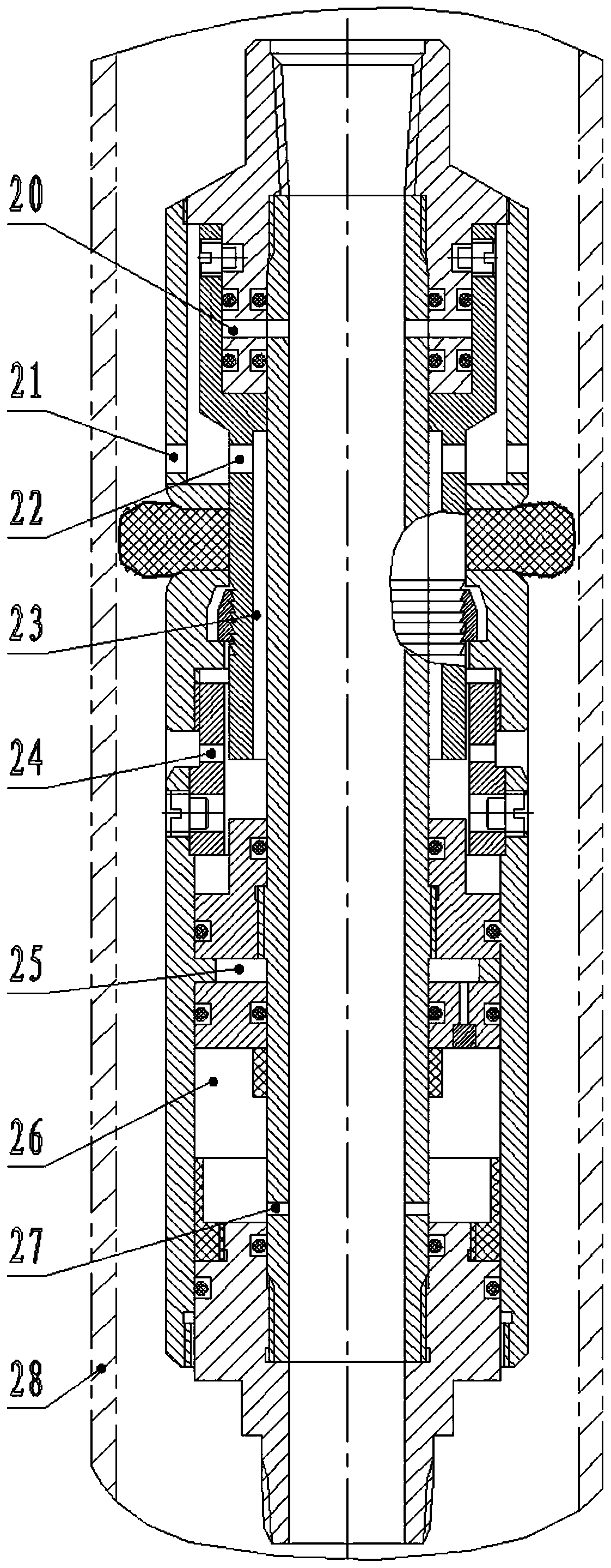
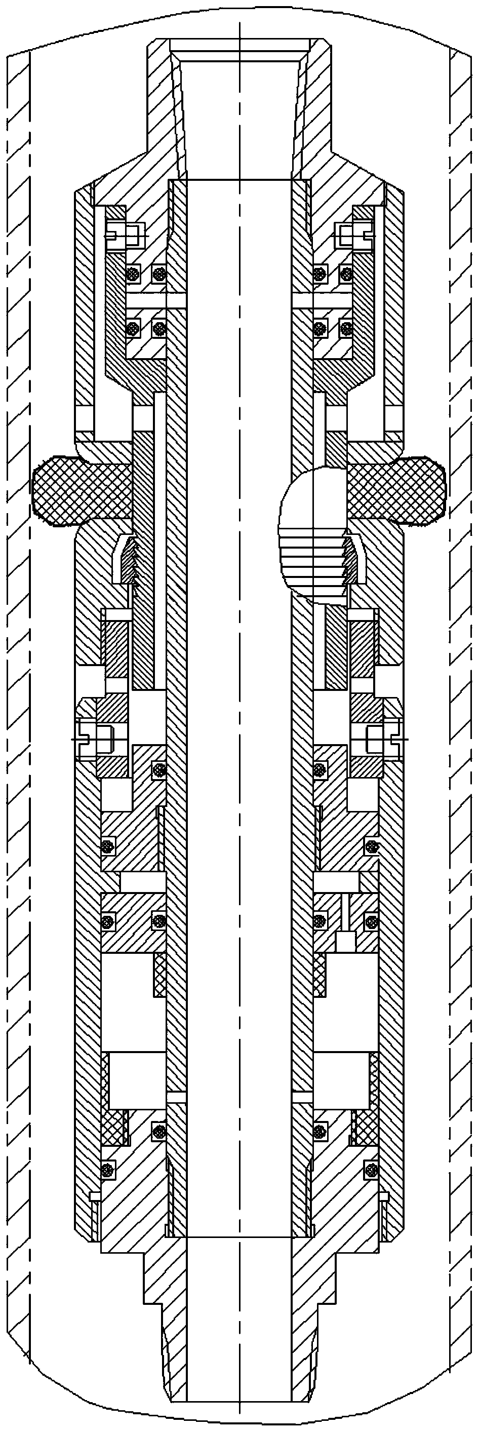

Image

  • Self-expanding automatic oil drain device
  • Self-expanding automatic oil drain device
  • Self-expanding automatic oil drain device

Examples


Embodiment Construction

[0017] The present invention will be further described below in conjunction with accompanying drawing:

[0018] Please combine the attached Figure 1-5 , This embodiment includes an upper joint 1, a central tube 5, a lower joint 18, an outer central tube 4, shear nails 2, an upper jacket 3, an elastic damping ring assembly 6, a circlip carrier 9, a circlip 8 and a lower jacket 12. The upper joint 1 is connected to the lower end of the tubing string, the upper end of the central pipe 5 is threadedly connected to the inner side of the upper joint 1, and the side wall of the central pipe 5 below the threaded connection and the side wall of the upper joint 1 corresponding thereto are opened. Oil drain hole 20 is arranged, and oil drain hole 20 communicates with center tube 5 inside, and center tube 5 inside communicates with the oil pipe string interior of this device top again, so oil drain hole 20 can drain the oil in the oil pipe string. The outer central tube 4 is set on the ...


PUM


Abstract

The invention belongs to the field of downhole tools for oil field production, and particularly relates to a self-expanding automatic oil drain device. The self-expanding automatic oil drain device comprises an upper joint, a central pipe, a lower joint, an outer central pipe, a shear pin, an upper outer sleeve, an elastic damping ring assembly, a clamp spring carrier, a clamp spring and a lower outer sleeve; the upper end of the central pipe is connected with the upper joint in a threaded mode, and oil drain holes are formed in the side wall, under the positions of the threaded connection, ofthe central pipe and the side wall, corresponding to the threaded connecting positions, of the upper joint; the outer central pipe sleeves the outer part of the central pipe and a ring cavity for liquid passing is reserved between the central pipe and the outer central pipe, and the ring cavity is called a liquid passing passage; the upper end of the outer central pipe sleeves the upper joint andthe oil drain holes are blocked; and the outer central pipe is connected with the upper joint through the shear pin, and the upper outer sleeve sleeves the outer part of the outer central pipe, and aring cavity is reserved between the upper outer sleeve and the outer central pipe. According to the self-expanding automatic oil drain device, the problems of tedious processes of pressing, repeatedly lifting and releasing a pipe string, throwing weights and the like of a conventional oil drainer are solved; and the automatic oil drain can be realized with the linkage of the pipe string, and theoperation efficiency is greatly improved.

Description

technical field [0001] The invention belongs to the field of downhole tools for oil production in oil fields, in particular to a self-expanding automatic oil draining device. Background technique [0002] With the in-depth development of the country's emission reduction, energy saving and environmental protection, the performance of some domestic oil drilling tools is falling behind the requirements of the times. Among them, the oil drainer used for oil draining in the process of pulling out the string is the most representative. . At present, there are generally the following problems in various conventional oil drainers: 1. The start-up process of oil drainage is relatively complicated, and operations such as pressurization by a pressurized vehicle, collision with heavy objects, and repeated lifting and release of pipe strings are required, which artificially causes objects to fall down the well. 2. Most of the oil drainage starting parts are made of carbon steel. When us...

Claims


Application Information

Patent Timeline
Patent Type & Authority Applications(China)
IPC IPC(8): E21B34/12E21B17/10C22C21/06
CPCE21B34/12E21B17/1014C22C21/06
Inventor 杨朝杰
Owner 大庆吉庆雨科技开发有限公司
Learn More