Bidirectional driving micro-mirror chip and manufacturing method thereof

A two-way drive and micro-mirror technology, applied in optical components, optics, instruments, etc., can solve the problem of not being able to form a two-way drive structure, and achieve the effect of excellent micro-mirror scanning effect.

Pending Publication Date: 2019-12-13
苏州知芯传感技术有限公司
View PDF2 Cites 3 Cited by
  • Summary
  • Abstract
  • Description
  • Claims
  • Application Information

AI Technical Summary

Problems solved by technology

The existing patent can only form a high and low two-layer comb structure, and cannot form a bidirectional drive structure

Method used


Image

  • Bidirectional driving micro-mirror chip and manufacturing method thereof
  • Bidirectional driving micro-mirror chip and manufacturing method thereof
  • Bidirectional driving micro-mirror chip and manufacturing method thereof

Examples


Embodiment Construction

[0039] The specific embodiments of the present invention will be described in further detail below in conjunction with the accompanying drawings of the specification.

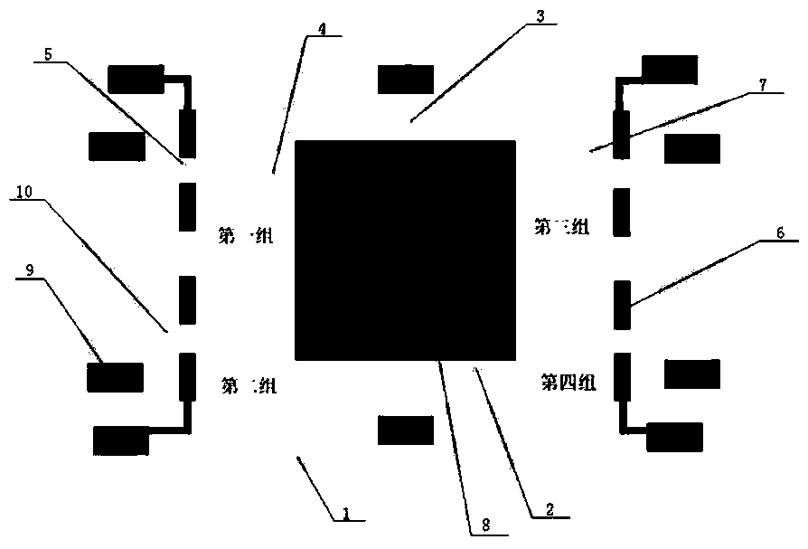
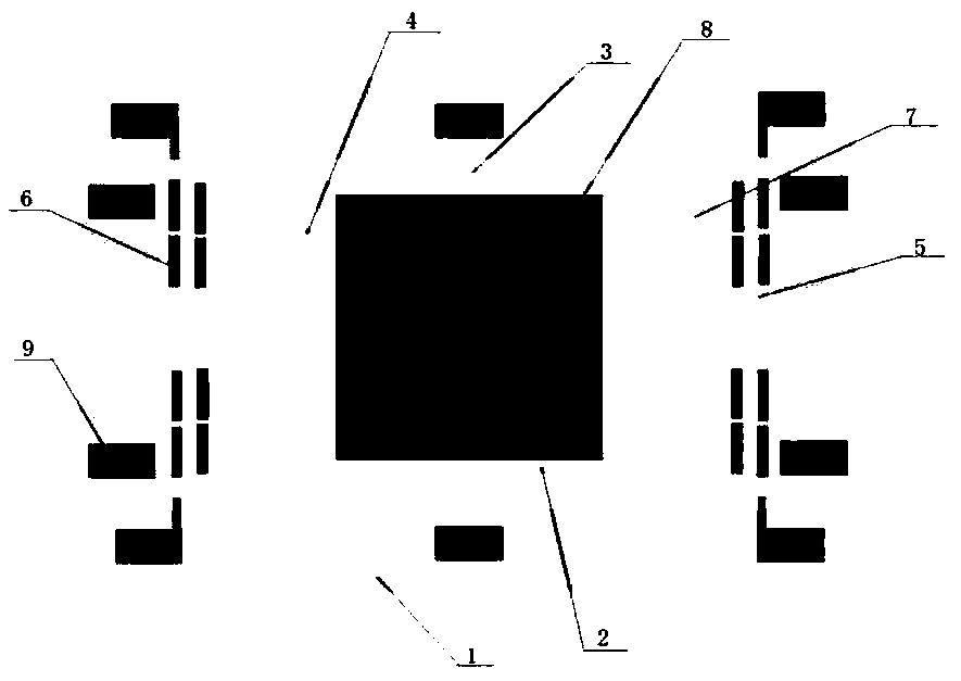
[0040] The present invention designs a bidirectional driving micromirror chip. In practical applications, it specifically includes a substrate 1, a mirror support 2, a rotating shaft 3, two sets of lower driving devices, and at least two sets of upper driving devices. The substrate 1 is SOI silicon. A ring structure made of a sheet of material, and the various parts of the substrate 1 are coplanar; the opposite sides of the mirror support 2 are respectively connected to the inner side of the ring structure of the substrate 1 through the rotating shaft 3 and the mirror support 2 is The straight line where the shaft 3 is located is the shaft freely rotating.

[0041] The two sets of lower driving devices respectively correspond to the opposite sides of the mirror support 2 on both sides of the line where the shaft 3 i...


PUM


Abstract

The invention relates to a bidirectional driving micro-mirror chip and a manufacturing method thereof. The problems that a two-layer comb tooth structure is adopted in the prior art, only one-way driving can be achieved, the stress of a micro-mirror is asymmetric, and the micro-mirror cannot completely rotate around a center shaft are solved. A brand-new design structure is applied, an upper-layercomb tooth structure, a middle-layer comb tooth structure and a lower-layer comb tooth structure are provided, two-way driving force is provided for the micro-mirror, and a better micro-mirror scanning effect is achieved.

Description

Technical field [0001] The invention relates to a bidirectional drive micromirror chip and a manufacturing method, belonging to the technical field of microelectromechanical systems. Background technique [0002] Compared with traditional machinery, the size of MEMS devices is smaller, generally on the order of microns to millimeters. It is based on the semiconductor integrated circuit (IC) manufacturing process, which can make large-scale, low-cost production using mature technologies and processes in IC production, which greatly improves the cost performance compared with traditional "mechanical" manufacturing technology. [0003] Commonly used MEMS driving structures include electrostatic driving, which are widely used, and the electrostatic driving mainly adopts a comb tooth structure. The comb tooth structure is generally divided into two types, one is the in-plane comb structure, used for in-plane structure drive, and the other is the upper and lower comb structure, used for...

Claims


Application Information

Patent Timeline
Patent Type & Authority Applications(China)
IPC IPC(8): G02B26/08G02B26/10
CPCG02B26/0858G02B26/105
Inventor 陈巧
Owner 苏州知芯传感技术有限公司
Why Eureka
Try Eureka