
Three-dimensional scanning device

A technology of three-dimensional scanning and scanners, which is applied in the direction of measuring devices, optical devices, instruments, etc., can solve the problems of high equipment operating costs, poor human comfort, high labor costs, etc., to reduce equipment costs, low cost, and easy assembly Effect

Pending Publication Date: 2019-05-21
HEFEI UNIV OF TECH
View PDF0 Cites 4 Cited by
  • Summary
  • Abstract
  • Description
  • Claims
  • Application Information

AI Technical Summary

Problems solved by technology

[0003] 1. The hand-held scanning method requires additional staff to complete the scanning work with hand-held scanning equipment, which has high work intensity and high labor costs;
[0004] 2. Scanning shed method, the scanning shed needs to install multiple scanners to realize 3D scanning, and the equipment cost is relatively high;
[0005] 3. The platform rotation method, the scanner is controlled to move up and down, and the platform is controlled to drive the scanning object to rotate to realize three-dimensional scanning. The scanned object needs to rotate with the platform. For the object to be scanned with a large mass, the corresponding energy consumption is relatively high. The operation cost of the equipment is high; and, if the scanning object is a human body, since the human body needs to rotate with the platform, when the scanning speed is too fast, the comfort of the human body is poor, and if the scanning speed is too slow, the scanning efficiency is low

Method used


Image

  • Three-dimensional scanning device
  • Three-dimensional scanning device
  • Three-dimensional scanning device

Examples


Embodiment 3

[0034] The working principle of the three-dimensional scanning device in this embodiment is as follows:

[0035] 1. Before scanning:

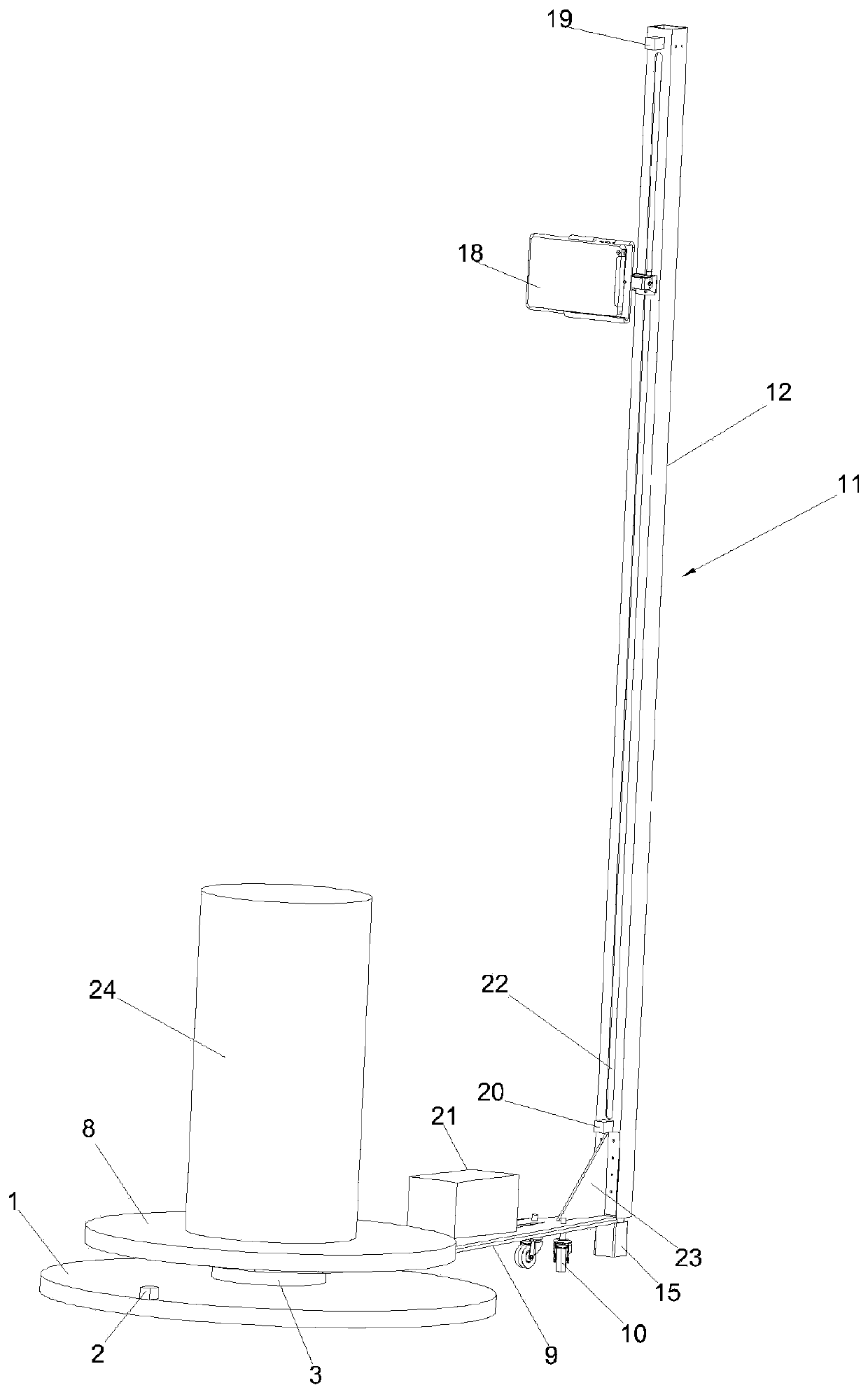
[0036] The object 24 to be scanned is placed on the center of the scanning platform 8. In the initial state, the scanner 18 assembly descends to the lower limit height, and the scanner 18 is adjusted to maintain a horizontal attitude through the steering gear 17;

[0037] 2. Start scanning:

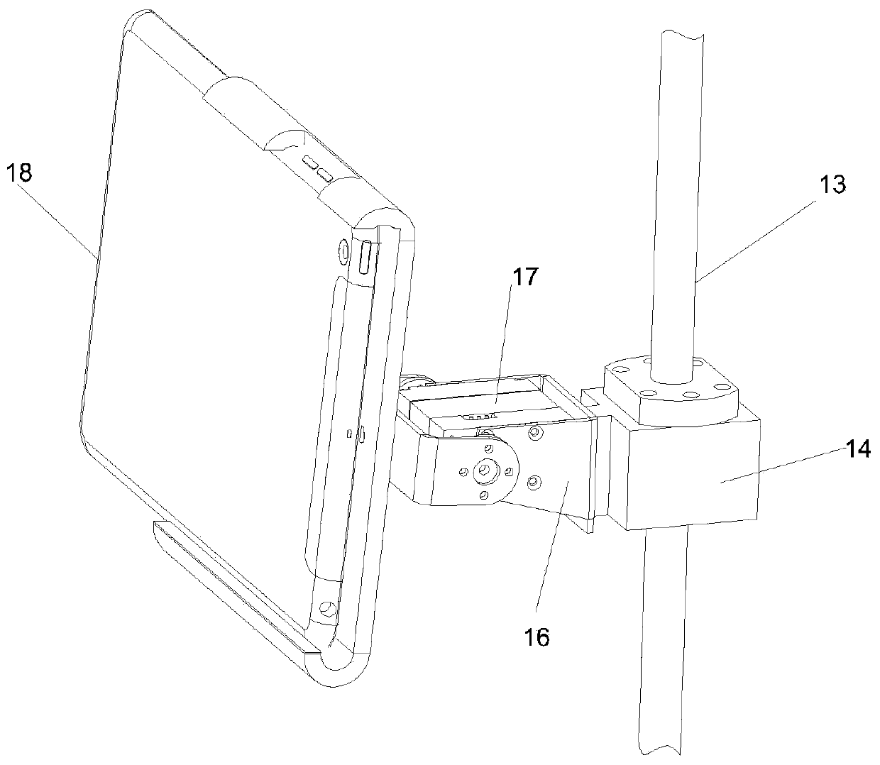
[0038] The stepper motor 15 drives the scanner 18 components to rise up successively, and the rotating scanning member is driven by the double-axis hub motor 3 to rotate, and the pitch angle of the scanner 18 can be adjusted by the steering gear 17 according to the scanning requirements;

[0039] After the scanner 18 assembly rises up for the first time, the rotary platform 9 rotates clockwise to the position of the rotary travel switch 2, and the scanner 18 completes the first scan of the object 24 to be scanned, and transmits the scan information to the...


PUM


Abstract

The invention provides a three-dimensional scanning device. The motor shaft of a dual-shaft wheel hub motor is vertically arranged; the bottom end of the dual-shaft wheel hub motor is installed at thecenter of a fixing base; the top end of the dual-shaft wheel hub motor is fixed at the bottom center of a scanning platform; one end of a rotating platform is connected with the outer edge of the wheel hub of the dual-shaft wheel hub motor; the other end of the rotating platform extends outwards along the radial direction of the motor shaft so as to be connected with the bottom end of a lifting mechanism; a servo is mounted on the lifting mechanism through a mounting bracket, the output shaft of the servo is connected with a scanner, and therefore, a scanner assembly can be formed; the pitchangle of the scanner can be adjusted by means of the driving of the servo; the scanner assembly as a whole can be driven to move up or down by the motor of the lifting mechanism, and can be limited during the upward and downward movement through an upper stroke switch and a lower stroke switch mounted on the lifting mechanism; and the rotating platform can rotate with the wheel hub with as the motor shaft adopted as a rotating shaft, and can be limited during rotation through a rotation stroke switch on the fixing base. The three-dimensional scanning device can complete three-dimensional scanning operation on the basis that an object to be scanned is motionless. The three-dimensional scanning device has the advantages of low processing cost and operational easiness.

Description

technical field [0001] The invention relates to a three-dimensional scanning device. Background technique [0002] At present, the 3D scanning operations at home and abroad mainly have the following three operation modes: [0003] 1. The hand-held scanning method requires additional staff to complete the scanning work with hand-held scanning equipment, which has high work intensity and high labor costs; [0004] 2. Scanning shed method, the scanning shed needs to install multiple scanners to realize 3D scanning, and the equipment cost is relatively high; [0005] 3. The platform rotation method, the scanner is controlled to move up and down, and the platform is controlled to drive the scanning object to rotate to realize three-dimensional scanning. The scanned object needs to rotate with the platform. For the object to be scanned with a large mass, the corresponding energy consumption is relatively high. The operating cost of the equipment is high; moreover, if the scannin...

Claims


Application Information

Patent Timeline
Patent Type & Authority Applications(China)
IPC IPC(8): G01B11/24
Inventor 甄圣超崔亚磊黄康孙浩何湘粤
Owner HEFEI UNIV OF TECH
Learn More