Laser scanning sampling device using paraboloid mirror for correcting scanning angles

A parabolic mirror, correction scanning technology, applied in optics, optical components, instruments, etc., can solve the problems of reducing the effective utilization rate of the laser, the first shortcoming is not improved, and the processing difficulty is very high, and achieves low processing difficulty and simple structure. , the effect of easy maintenance

Inactive Publication Date: 2013-05-08
SOUTHEAST UNIV
View PDF4 Cites 4 Cited by
  • Summary
  • Abstract
  • Description
  • Claims
  • Application Information

AI Technical Summary

Problems solved by technology

However, this design cannot eliminate the effects of the second and third shortcomings, and reduces the effective utilization of the laser
[0010] The design of the cylindrical rotating mirror as the light deflector can also solve the second and third shortcomings well, but it does not improve the first shortcoming. At the same time, its processing is also very difficult, the process is complicated, and it is not easy to realize.

Method used


Image

  • Laser scanning sampling device using paraboloid mirror for correcting scanning angles
  • Laser scanning sampling device using paraboloid mirror for correcting scanning angles
  • Laser scanning sampling device using paraboloid mirror for correcting scanning angles

Examples


Embodiment

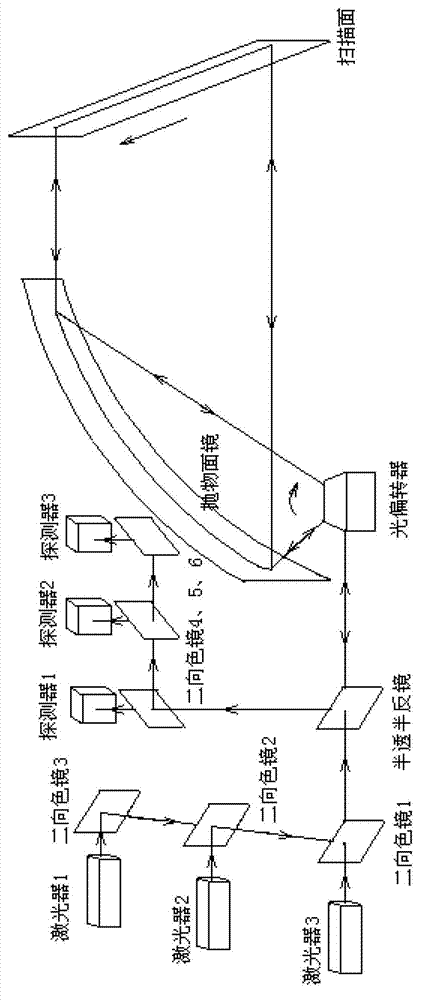
[0043] Such as figure 1As shown, a laser scanning sampling device using a parabolic mirror to correct the scanning angle includes a laser group, a dichroic mirror 3, 2, 1, a half mirror, a detector group, an optical deflector, a parabolic mirror, a dichroic Chromatic mirrors 4, 5, 6 and detectors 1, 2, 3. The laser group includes laser 1, laser 2 and laser 3 that emit red light, green light and blue light respectively. The laser light emitted by these lasers is combined by dichroic mirrors 3, 2 and 1 respectively and then emitted from dichroic mirror 1 to half-mirror, and then to the light deflector. The laser beam is deflected by the deflector to scan at a certain angle (50 degrees in this embodiment). These scanning lasers at different angles are reflected from the focus of the parabolic mirror, and after being reflected by the parabolic mirror, a parallel scanning laser is formed. Normal incidence to the scanning plane. The part of the mixed optical signal scattered at t...


PUM


Abstract

The invention discloses a laser scanning sampling device using a paraboloid mirror for correcting scanning angles. The laser scanning sampling device using the paraboloid mirror for correcting the scanning angles comprises a laser group, a beam combiner group, a semi-transparent and semi-reflective mirror, an optical deflector, a paraboloid mirror, a dichroic mirror group and a detector group, wherein lasers with different wavelengths are emitted by the laser group, combined by the beam combiner group, and emergent to the semi-transparent and semi-reflective mirror, the lasers are divided into transmission lasers and reflection lasers by the semi-transparent and semi-reflective mirror, wherein the transmission lasers are deflected by the optical deflector to form scanning lasers with a certain angle, after the transmission lasers are reflected by the paraboloid mirror, the formed parallel scanning lasers are vertically incident to a scanning face, parts of laser signals scattered by the scanning face return to the optical deflector along an original light path and then are reflected to the semi-transparent and semi-reflective mirror through the optical deflector, and laser signals with the different wavelengths are sent into the detector group through the dichroic mirror group. The problem that under the non-vertically incident condition, laser information decays along with the increase of an incident angle of the scanning lasers is solved.

Description

technical field [0001] The invention relates to a laser scanning sampling device, in particular to a laser scanning sampling device which uses a parabolic mirror to correct the scanning angle, uses an optical deflector to deflect the laser beam, and then reflects the scanning laser perpendicular to the scanning surface through the parabolic mirror; The light signal reflected by the scanning point at each moment is returned through the original light path, and finally sent to the detector group for reception. Background technique [0002] With the rapid development of various laser spectroscopy technologies, laser scanning sampling technology has become increasingly mature and widely used in scanning imaging, image printing, projection, mineral detection, food testing and many other fields. At present, the commonly used laser scanning sampling technology uses semiconductor lasers. Through the design and construction of optical paths, it cooperates with optical deflection devi...

Claims


Application Information

Patent Timeline
Patent Type & Authority Applications(China)
IPC IPC(8): G02B26/10
Inventor 叶莉华王文轩吕昌贵赵翀王叶轩崔一平
Owner SOUTHEAST UNIV
Why Eureka
Try Eureka